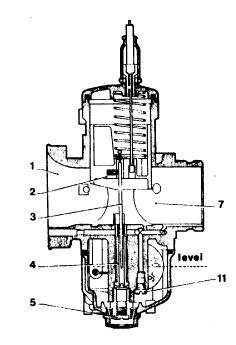
1 - air intake
2 - throttle valve
3 - tapered needle
4 - atomiser and needlejet
5 - main jet
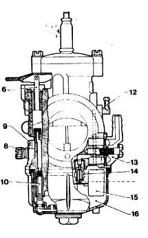
6 - starting device
7 - venturi
8 - idle speed adjusting-screw
9 - idle mixture adjusting-screw
10 - starter jet
11 -idle jet
12 - float chamber vent
13 - fuel inlet banjo union
14 - needle valve
15 -float
16- float chamber
fig. 1
2.2 Operating ranges. Scheme of phases while running
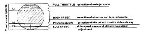
fig. 2
Figure 2 shows the section of a venturi according to the operating periods regulated by the throttle valve opening. In every phase of operation, it is possible to vary and select the optimum setting.
In the idle stage, the idle circuit and idle adjustment is set with the mixture screw and idle-speed screw.
In the "B" progression phase, fuel mixture delivery from the idle hole is steadily replaced by mixture delivery from the progression hole, drawing emulsion mixture from the idle circuit, and in this range, choosing the correct idle jet and throttleslide cutaway is necessary. The throttle valve cutaway slightly affects the carburation up to about half throttle.
In the "C" high-speed period, mixture delivery from the idle circuit and from the progression hole is replaced by mixture from the main circuit and selection of both the atomiser and the tapered needle should then be made.
In the "D" period of full throttle and, with all the circuits of the earlier periods operating correctly, the size of the main jet is now finally selected.
2.3 Installation angles
The tapered-needle-type carburettors with concentric, central float chambers have a horizontal main barrel and can be mounted up to a maximum inclination of 40 degrees from the horizontal (figure 3).
For applications on motocross and trials engines, etc, this inclination should be 30 degrees or less.
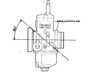
fig. 3
2.4 Engine connections
The carburettor is usually connected to the engine with one of the following:
A-male clamp fixing (figure 4)
B-female clamp fixing (figure 5)
C-flange fixing (figure 6)
— the male clamp connection used for the flexible fixing of the carburettor to the engine is usually recommended on motorcycles for motocross, trials, etc or fitted to engines which run to high rpm or those which produce strong vibrations.
— the female clip connection and the flange connection, with a rigid fitting to the engine, are usable on road motorcycles or fitted to engines which do not generate very strong vibrations.
Note that with the female clamp fixing and the flange connection, as you can see in figure 5 and 6, there is also the need to provide both effective heat insulation and a perfect airtight seal.
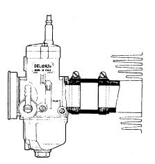
fig. 4
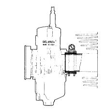
fig. 5
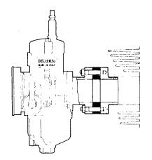
fig. 6