The Life Energy | The Rotorgon | The Orgonometer | The Magnetorgon | Tables and Figures | The author | PDF version | Old Site (only italian) | Main Page

Tables and Figures


THE ROTORGON


_ _

fig. 1A - The direction of the rotor rotation varies according to the sign of the charge of the ions contained in air (pictures 1 and 2) and the orientation of the instrument (pictures 1 and 3)

ROTORGON
Pos. Denomination Material  
1 Cup nut (Dado cieco) 1 Brass Ottone
2 Screw 5 MA (Vite) 1 Brass Ottone
3 Flange 1 Brass Ottone
4 Revolving half a box 1 Board Scatola orientabile
5 Base 1 Wood Legno
6 Top end lock 1 Brass Disco di chiusura


Table 1
 
Rotor ASSEMBLY
Pos. Denomination Material
1 Tapered pin (Perno a spillo) 1 Steel (acciaio)
2 Manifold disk (Disco collettore) 1 Board (cartone)
3 Rayed bearing - n.3 wires (Raggiera a 3 bracci) 3 Copper (rame) Ø 0.3 mm
4 Paper ring (Carta Vergatina) 1 Manifold paper
5 Conical seat milled 1 Brass (ottone)
Table 2
 
Table 2a
 
Table 3
 
Table 4
 
Table 5
 

THE ORGONOMETER

Table 6-7
 
Table 8


THE MAGNETORGON


[Scala: 1/2]

Fig.1
 

Fig.2


Fig. 3 - A charged particle entering a uniform magnetic field H with direction v, goes along a cylindrical helix trajectory, having as axis the direction of the field

 
Measurements of the potential difference in mVolt between the central column and the internal iron sheet through an auxiliary battery


D.C. A.C.
Rotorgon 15,2 218
Iron sheet 8,9 170
 

Two experiments were performed. The former using the Rotorgon Mod. RO-6 and the latter by using an iron sheet, of the same size of the device stator, but without the accumulator. In the first experiment the potential difference, measured with the dial of the multimeter on the DC rate, is 70% higher than the one measured in the second experiment (iron sheet only). The potential measured in the Rotorgon with the dial on AC, was 28% higher than the one measured between the central support and the iron sheet. The auxiliary battery supplied a tension of 63 Volt.
These tests would prove the volume inside the Rotorgon has a higher charge of ions than it is available in air, having constant all the other variables. This higher conductivity inside the stator seems to be attributed to the presence of the small orgone accumulator.

fig. 4


Study on the electrical properties of the Rotorgon

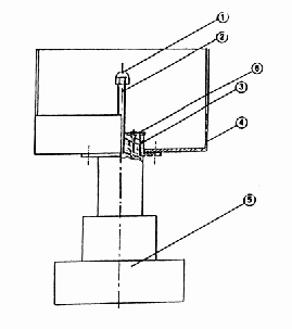
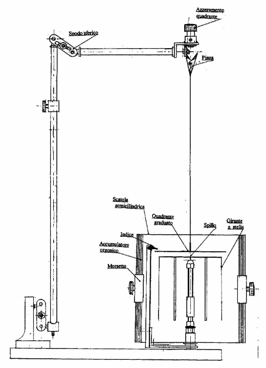
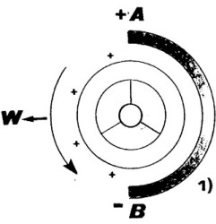
If we connect the device to a condenser we can see that, after some times, the condenser is charged. The two 
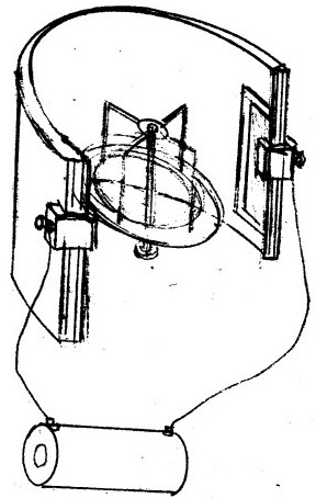
walls of the condenser will have to be connected to two metallic plates fixed to the border of the box, after having interpose, between the border and plate, an insulating layer (see attached figure). We used for the purpose two aluminium strips, glued to two rectangular streams of cardboard (3 cm x 10 cm). These two electrodes are fixed to the borders by means brass clamps. At the beginning of the test, at 6,45 pm, the 60 mF condenser, was discharged. After 5 minutes, by using a tester connected in parallel, an increasing reading of 34 mVolt was found.
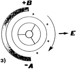
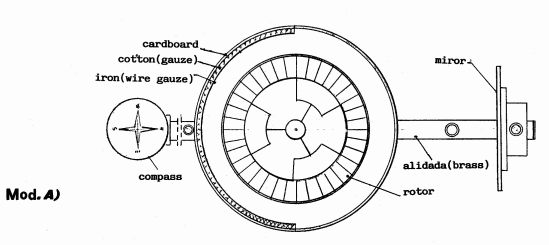
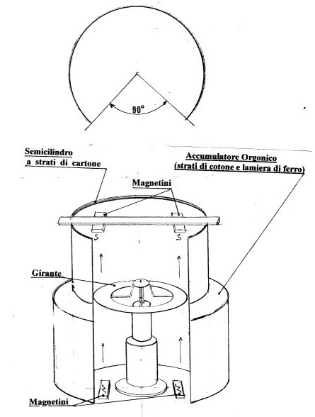
We tested on the RO-6 Model (opening angle of the box of 120°), whose rotor rotated all the time of the test in counterclockwise, with swinging motion (accelerated and decelerated) and with an average velocity of 12-14 round per minute. The device was west-oriented.
Test condition. Time: 6,45 pm, internal temperature: 22 °C, internal relative humidity: 41%, pressure: 766 mmHg.
At 7 pm the tension was 46,5 mVolt, at 7,27 pm it increased to 50,5 mVolt, and at 7,37 pm it was 50,8 mVolt. After 1 hour from the beginning of the test, namely at 7,45 pm, the reading was 51,5 mVolt.
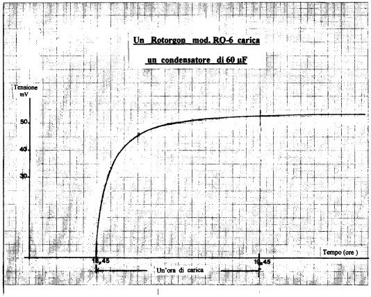
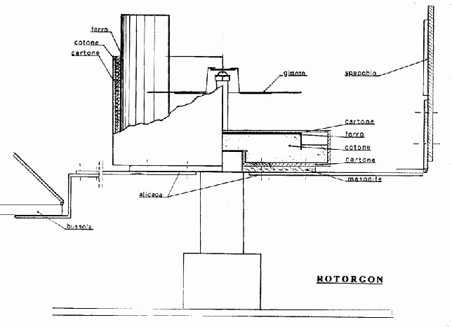
fig. 5


The Rotorgon is charging a condenser

fig. 6


Trial test with Rotorgon RO-6

fig. 7 - Set-up for the condenser charging test through the Rotorgon RO-6