The measurement of the energy that passes through the Rotorgon
requires the use of an instrument allowing us to perform the
measurements, even tough in an approximate way, and that we can easily
build, using easy-to-find materials, such as we did for the Rotorgon.
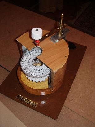
Essentially, we have to provide the Rotorgon with a graduated quadrant,
to be fixed to the semi-box some millimetres above the rotor. A
suitable index, to be mounted suspended by a wire above the quadrant,
will allow us to read on a conventional scale the quantity we are
measuring. Hereafter we show the details as to realise this additional
part of the instrument.
Firstly, we should cut out from a paper sheet, or from a thin
cardboard, a graduated circle (with divisions of 10°), drawn by
using a goniometer. This quadrant will have a external diameter equal
to that one of the rotor and internal diameter of about 3-4 cm. The
graduation (0-180°) should be drawn both on the left and the right,
as it should be read in both the directions of the index rotation. The
quadrant will be fixed to a disc (made of cardboard or plastic
material, metallic materials must be avoided) that is connected to the
semi-box wall, by using a post connected to a tightening clamp.
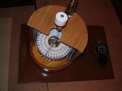
Particular care in the construction of the index is required. The
accuracy in the measurements of the instrument depends on its weight.
It can be made of a thin cardboard or a thin cellophane sheet.
Essentially, it consists of a rectangular strip (15 mm large)
tip-shaped at one end and provided with a central hole. A bush
footstalk, set through this hole, is used to house a needle, the eye of
is tied to the suspension wire. This last one is a very thin nylon wire
(0.06 mm thick, and 4-5 mm long) that can be bought in a field sports
store, usually as fishing line. The upper end of the wire will be tied
to a sewing needle fixed to a banana plug (to be found in an electronic
equipments store). Then, the banana plug will be housed in a bush
mounted to the end of a horizontal arm fixed to the mounting of the
tightening clamp.
By using this last device little upwards and downwards adjustments of
the index of some millimetres against the quadrant plane could be done.
Above all it will be possible, by rotating the banana plug, to zero the
index. This operation consists of making the index tip and the zero on
the quadrant scale to coincide. It is suggested to perform this
operation before to carry out each series of measurements. The
performances of the instrument improve a lot when the inner end of the
index is provided with a little strip of an arc of circle-shaped paper,
with a width of about 40-50 sexagesimal degrees. Naturally, the loads
along the index rod will have to be balanced at the attachment point of
the wire.
How to make the readings with the
Orgonometer
When the orgonic energy passes through the instrument, it acts
on and affects both the rotor and the index. Both will move with a
simultaneous motion and at the same velocity. Nevertheless, gradually
the rotation goes on, we can observe that the motion of the rotor,
after a first phase of accelerated motion, is tending to assume a
constant velocity. In this first phase the index of the instrument
makes the forwards run until its maximum excursion, in correspondence
with the start of the uniform motion of the rotor. At this point the
index stops while the rotor continues to rotate. This is the time to
make the reading.
In fact, at this moment the equilibrium between the motor torque,
exerted by the energy we want to measure, and the frictional torque due
to the elastic reaction of the nylon wire is realised. This last
behaves like a torsion spring that tends to oppose to the motor torque
exerted on the wire from the index, subjected, like the below rotor, to
the action of the orgonic wave. To the maximum excursion of the index
corresponds the maximum value of the energy of the wave detected by the
instrument, measured in sexagesimal degrees. Under the recall action of
the wire (whose torque now is greater than the motor one) the index
starts its backwards motion towards zero. The index has concluded a
complete run. In the point at which the index comes back to zero, the
energy resumes the minimum energy had at the forwards run. If we
measure the time the index employ to make a complete run we can know
the period of the orgonic wave and the time employed by the wave to
make a complete oscillation.
Knowing this data (the period), and the velocity of the wave
propagation, we can obtain its wavelength. It is something like we have
already previously seen when we discussed the measurement method of the
time interval separating two consecutive minimum of the rotation
velocity of the Rotorgon rotor. In fact, the value previously obtained
of T=25 sec has found confirmation in counting the time of a complete
oscillation of the quadrant that, at constant regime, has resulted to
be exactly 25 sec.
At this point it could be more correct to speak about a bundle of
waves, since, as we already previously mentioned, we think that each
instrument, according to its construction characteristics, is able to
detect and select a particular bundle of orgonic waves, where a
particular wavelength prevails on the others.
It can happen that the index, after reaching the maximum excursion
point, while it is making its backwards run, can stop and then restart
a new forwards run. In this case the instrument shows an abrupt
increase of the energy determined by an ascending branch of the wave
before it reaches its minimum.
Instantaneous value of the energy
If we want that the angular excursions of the quadrant are slow,
we have to adequately increase its moment of inertia. We can not
increase the diameter, that must be within 9 cm, considering that the
diameter of the box, in which the quadrant is located, has a diameter
of 12 cm, and can be lined with the planned layer for the accumulator
(naturally, we are referring to the most common used mean sizes, the
choice of which is forced by the size of the rotor, whose weight should
not be exceed 0.4-0.5 grams). In this way we are forced to act on the
weight and for this reason it is suggested to cut out the quadrant
directly from a cardboard (Bristol type).
Using this expedient we will observe that, when the rotor assumes an
uniform motion, the quadrant stays for long time on the value that
corresponds to this velocity, without being subjected to periodical
oscillations. This allows us to perform a reading that is very close to
that of the instantaneous value of the energy in that moment passes
through the instrument.
Once the reading is done, we can express it in function of the adopted
measurement unit. As of today, waiting this unit is confirmed, we can
use the org (abbreviation of orgone). In our case one org corresponds
to one sexagesimal degree, having the quadrant been divided in
sexagesimal degrees.
However, for a given model, the angle of rotation of the quadrant under
the action of the orgonic wave, is only function of the torque that
moves it, being able to group all the other parameters (length,
section, and material of the wire) in only one constant, that is just
the constant for that model.
However, the energy we are measuring is polarised, in that it has a
positive and negative sign, depending on the direction of rotation
(clockwise or counterclockwise). It has been assumed as positive sign
the counterclockwise direction of rotation because it has been seen
that this is the natural motion of the moving equipment when the
instrument is west-oriented. In this case the portion of the quadrant
on which we will perform the reading is that located on the right side.
On the contrary, if the motion has clockwise direction, the reading
should be done on the left part of the quadrant (hence the reason why
we need a mirror-like numbering along one diameter). So, for instance,
if the quadrant stops and stays for a while at 40° of the right
semi-quadrant, the reading is +40 org.
Up till now, we have generically spoken of orgonic energy, without
doing explicit reference to the source it stems from. Nevertheless, the
Orgonometer can find an own application also for measurement of the
energy radiating from the hands, provided that also in this case the
constraints observed for the use of the Rotorgon are still valid.