|
|
|
|
|
|
an electronic key that fits your pocket and requires no batteries Smartcard-controlled Relaya clever pirate-card application What is it | Schematic | Truth table | Prototype | Smartcard, how to get and program one | Linked projects
|
 |
This card-activated realy requires just an handful of parts and is very simple. The active components in addition to the Nutchip are a 74HC00, a reset generator (IC3) and a transistor for relay switching.
Thereset integrated circuit IC3, an MC34064 from Motorola, guarantees a clean Nutchip RESET even in presence of electric noise coming from the power network. Its duty consists of discharging the capacitor C2 as fast as possible when a power drop is detected.
The Nutchip (IC1) is the heart of the device. Nutchip output OUT1 drives an LED (LD1) which is in series to a current-limiting resistor (R3). A separate output is used for dirving the relay (RELAY1) through a transistorized relay driver stage (TR1, R2, D1). The transistor works as an electronic switch, amplifying Nutchip output current from tenths of mA to tens of mA - a level suitable for driving the relay coil. Diode D1 protects the circuits from high voltages that are induced on the coil during switchoff.
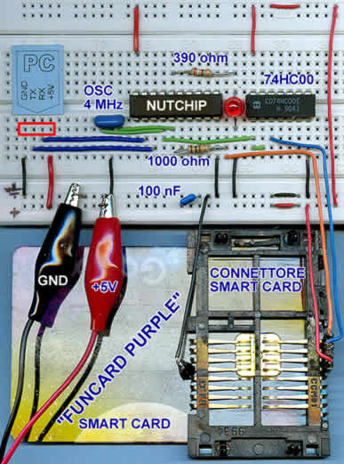
Schematic diagram. For simplicity's sake, card is depicted as viewed from top: the actual connection is provided by means of a special slot connector.
But let's introduce the smartcard. We choose a "Funcard Purple": this is the usual name for a card embedding a powerful processor, an Atmel AT90S8515, and a serial EEPROM memory. Other "Funcards" similar to the "Purple" are the "Funcard Prussian" and "Funcard Prussian 256": these should be theoretically compatible, although more expensive. However, please note that we have not tried them, so take our word at your own risk.As the Funcard Purple embeds a microcontroller, you must load it with a program written for this specific task before using it in our circuit. The program is a free download from the file "card_1234.hex", and we supply it ready made so you need only a programmer to get up and running. Once programmed, the Funcard's microcontroller will act as a remote control, generating a pulse train undistinguishible from a radio (RF) remote control. The resulting waveform is output on the smartcard pad labelled "OUT, which connects -though a suitable slot connector- to the Nutchip remote control input (REMOTE, pin 6). We placed a series resistor, R4, in order to protect the Nutchip from noise and spike pulses that can be generated during card insertion and extraction.
For semplicity's sake, the schematic diagram does not show the smartcard connector: instead, the smartcard picture is shown as it appears looking at it from the golden pads side.
- Card power is 5 volts and must be connected to the pads labelled as +5V (positive) e GND (negative).
- Card output signal is available on the OUT pad, ready to be decoded by the REMOTE input of the Nutchip. Don't omit a current-limiting resistor, R4, as it limits peaks that may happen while moving the card.
- As every processor, also the microcontroller embedded in the card needs a clock source. We provide a 4 MHz clock borrowing it from Nutchip's main clock, which is available on pin 4 (XTAL2). The clock passes through one of the 4 NAND gates from IC2 (a fast-CMOS logic circuit type 74HC00), which is connected in a classic inverter configuration. This logic gate adapts clock impedance, and decouples Nutchip clock from the external world. Decoupling is required to protect the citrcuit and to prevent the main clock from being stopped should a wrong memory card be inserted.
We suggest to connect free gates inputs (there are 3 unused gates left from IC2, corresponding to input pins 4,5,9,10,12,13) to the negative power rail. This gates are high-impedance and should not be allowed to "float": caonnecting to GND avoids any floating.
The truth table which implements our smartcard-controlled relay counts just a few rows. It is very similar to any truth table implementing a remote control with a Nutchip;
- When idle the device sits on state st00 - which is also the power-on status. This status waits for one condition: remote control key 1 to be pressed. The Nutchip cannot tell whether a "true" remote control or a smartcard replica is connected to its REMOTE pin.
From truth-table first row, you can easily see that as long as the Nutchip stays in st00, all outputs are low (0). As soon a the key1 code is received, Nutchip passes to state st01.- State st01 is the active state: all outputs are logic 1 (high), causing the LED (powered from output 1) to lit and the relay (driven by output 4) to energize. Notably, this state includes a condition on key1 which states st01 itself as next state. This is a trick to restart the 100 mS timeout as long as the key1 code is received, so the output is continuously excited when the card is inserted. Removing the card allows the timeout to expire, bringing the Nutchip back to state st00.
You can type in the truth table or load it from file card.nut: it is just a starting point. It is easy to change it to get -for example- a longer timeout after removing the card, on to implement an on/off relay behaviour, so that a first card insertion causes the relay to switch on, a second one switches the relay off, and so on.. Another useful addition could be a second relay, with different timings: examples of this can be found on parking lot gates, when a first output opens the gate and an auxiliary one switches on the light. Well, more experienced users will now begin to see how to include a photocell in order to get the light on only at night... This is the beauty of Nutchips: start simple, and grow gradually adding more features!
Stop dreaming, let's continue with our description, and don't forget to set the remote control type to "Custom RF" and to input the correct key1 code. The code must be the same as the one programmed on the smartcard. Default code for our file card_1234.hex is 1234; instructions to chage this code are included in the same .zip file.
|
|
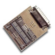
Smartcards, connettors and programming
|
|