|
|
|
|
|
learn how to drive 7-segment displays
7-segment displays | 4511 display driver | Assembling | Truth table | Like a dice
This project introduces a fundamental electronics building block: the counter. Building yourself a simple circuit which increments display count every second, you are going to learn how displays work and how to drive them in the right way. For those who already know how to drive display and counters , we suggest to skip this section and jump to the second part of the article, which uses a counter to implement a reaction-time game.
Schematic diagram of the counter. Adding two pushbuttons to we can transform it in a reaction time game and other useful designs! |
A 7 segment display is manufactured encapsulating 7 LEDs inside a single case. Each LED is given a shape and position which makes it a separate "segment": lighting teo or more segment in different patterns, we can read all digits from 0 to 9 on the display.
Segmenfs are conventionally identified with letters from A to G. The schematic diagram above shows the correspondence between segment position and the letter. For example, number 2 is obtained lighting segments A,B,G,E,D, whereas number 3 requires segments A, B, C, D, G. If all seven segments are lit then a number 8 is obtained.
Despite of its name, practically all modern 7-segment displays contain 8 LEDs! This eitghth segment is required for the decimal point, and it is conventionally labelled "H" or "DP".
To reduce pin count from 16 to 9, almost all 7-segment displays connect together one pin from all of the internal LEDs bringing it to a single display pin. In the case of so called "common cathode" displays, all cathodes are connected together and to the common cathode pin, while the anodes are connected to segment pins indifdually. The opposite for "common anode" displays.
The TFK214 display we selected for this projects is a common cathode 7-segment display. The catodhes are connected to pin 3, with anodes of segments A,B,C,D,E,F,G,H to the remaining pins. Pin 6 is connected to the common cathode as well; you need to connect only one to the negative supply. You can try to light any segment up as you do with any other LED.
You can replace the TFK214 with any other common-cathode display, provided you change the connectionsto adapt for the new pinout.
The pinout for the TFK214 follows:
| pin | segment |
| 1 | G |
| 2 | F |
| 3 | common cathode |
| 4 | E |
| 5 | D |
| 6 | H (DP) |
| 7 | C |
| 8 | ccommon cathode |
| 9 | B |
| 10 | A |
TFK214 pinout
The CD4511 IC is a specialized part very popular among electronics enthusiasts. It is cheap and easy to obtain from specialized stores.
Its purpose is to "read" a binary number from its inputs .A-B-C-D. An internal decoder converts the binary number into the 7-segment pattern required to display the number; 7 output stages, connected to output pins A through F, supply enough current to drive any ordinary common cathode 7-segment display. The decimal point is ignored by the driver.
Like the Nutchip, the 4511 works according to a truth table:
|
|
|||||||||||||||||||||||||||||||||||||||||||||||||||||||
The CD4511 reads the binary number on its inputs, decodes it and drives the segment outputs accordingly. |
||||||||||||||||||||||||||||||||||||||||||||||||||||||||
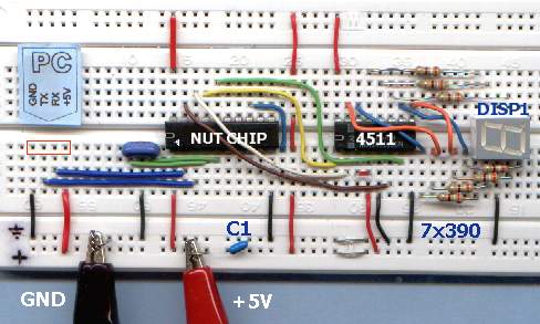
The prototype can be assembled on a solderless breadboard. The circuit is not a difficult one, but special care is required in order to complete all the connections. Also, be careful not to reverse any of the polarized parts (display, Nutchip, 4511). You can replace the TFK214 with any other common cathode display: should you use an equivalent, double check the pinout as it may differ from the TFK214.
A quick check can be performed using a 1000 ohm resitor and a 5 volt power source. Connect the resistor in series with the positive rail; then connect the negative rail to the pin supposed to be the common cathode, Next, touch the other pins with the free lead of the resistor. Each time you touch a new pin, a new segment should turn on. If none of the segments lights up, chances are that the negative rail is connected to a pin other than the negative rail. Try different pins until some segments lights up. Repeat this procedure until all of the pins are discovered, taking note for future reference. Note also that some display have more than one pin connected to the common cathode.
If your display pinout matches the one for TFK214, you can use the following picture as a guide, otherwise fit the resistors in orders to suit the display's pinout:
the circuit assembled on a solderless breadboard |
Parts list:
|
The truth table for the counter is very simple. It's as simple as letting the outputs take the binary values corresponding to the numbers from 0 to 9, changing state sequentially each and every second.
You can find the binary values to be assigned to the outputs from the 4511' truth table. Enter these values to the states st00 to st09, but there is a trick: as Nutchips require the output 1 to be written on the leftmost position, opposed to the usual way of writing binary numbers. This is why the outputs appear mirrored in the truth table: e.g. the number 3 is 0011 in binary, nad is written as 1100 in the truth table.
Anyway, you don't need to bother about the details as you can download the completed truth table from the file counter.nut :
Truth table for the 1 seconds counter.
Once you master the technique for building counters, you can employ it in a number of useful circuits: