|
|
|
|
|
Going Nuts in three simple designs: |
Get to know Mr. Nutchip with a simple LED flasher.
An easy and fun experience to get in touch with all the details of design and experimenting with Nutchips.
OUT1, OUT2, OUT3 and OUT4 are the four Nutchip outputs. Each output can be either at logic level zero or one.
Putting an output to zero (aka low level) means that its respective pin measures about zero volt. In this condition a Nutchip output can sink up to 10 mA.
Opposite to low level, an output at logic level one (aka high level) presents on the pin a voltage close to the power supply, about 5 volt for Nutchips. An output can source up to 10 mA.With Nutchips, the output states are not fixed by the manufacturer: you decide wich combination of zero and ones are appropriate for the outputs. You write a truth table in which every outputs combination is bound to a specific combination of the inputs and internal state. The more states you add to the table, the more different combinations you can get for the outputs. We will get back on this topic later.
Aa single output will suffice to make a LED flasher
We connect the LED to the output #4 (OUT4) of the Nutchip, connecting its other pin to the positive rail through a 390 ohm series resistor. LEDs must always have a resistor connected in series, in order to limit maximum current.
This type of "reverse" connection is recommended for most digital IC, nonetheless it adds a little magic to the circuit. As opposed to popular belief, the LED will be ON with the output at zero volts!A three pin ceramic resonator provides the clock pace for the system to work. To complete the circuit, a 100 nF capacitor is required by the chip for smoothing noise on the power supply.
In order to keep the circuit simple, we will connect the reset pin to the positive, leaving other pins unconnected except for the RX and TX pins as they serve for downloading the truth table into the Nutchip. The pins required for chip programming are grouped in the "programming port": this is where the PC interface will plug.
A regulated 5Vdc power supply is required, with the positive to +5V and the negative to GND.WHY THE LED IS ON WHEN THE OUTPUT IS OFF?
A LED is a diode that emits light when it is traversed by a current ranging from 1 to 20 mA. A way to make a current flow through a device is to connect it between a positive and a negative poles. Here the positive pole is the positive supply rail, namely +5V, while the negative pole is connected to the ground, represented by a sort of arrow (see pin 10).
An output at logic level one measures +5V, the same as the positive pole. Connecting an LED between the positive and an output at the same voltage as the positive pole does not provide any current flow for the LED. The LED is OFF.
What if the output goes to logic level zero? Logic zero is zero volt, the same as the negative pole. Connecting an LED between the positive pole and an output at the same voltage as the negative pole provides the current flow to turn the LED ON.
Magic, isn't it?
As for the LED polarity, always remember that the arrow in its symbol must point in the direction of the current flow, that is from positive to negative.
PARTS LIST
- DL1: LED diode
- R1: 390 ohm resistor
- OSC: 4MHz, three-pin ceramic resonator
- C1: 100nF ceramic capacitor
- IC1: Nutchip NUT01-AK or NUT01-DEA
Other tools required: 5Vdc stabilized power supply, solderless breadboard, Nutchip programming interface, some thin insulated wire for connections, and a PC running Nutstation.
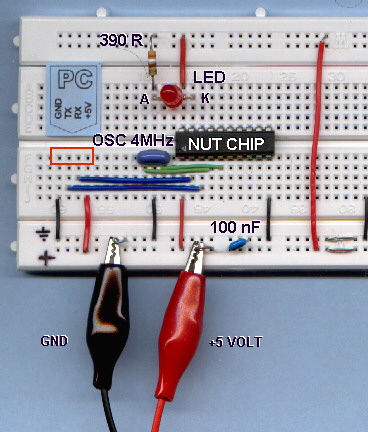
Schematic of the LED flasher
The circuit is very simple, and can be built on a solderless breadboard.
Be careful not to reverse the Nutchip, its pin 1 must be correctly aligned: the picture shows it in the lower left corner relative to IC body, near to the ceramic resonator (OSC).
Nutchip pin 1 is also marked by a small slot or a dot on the IC case, and looking it afrom above,the other pins have increasing numbers running counterclockwise.
LEDs have a polarity too: the catode (K) is the pin with the bar in the schematic. This pin is usually shorter, and the case has a flat face near it. The anode (A) is the pin with the arrow symbol in the schematic.
Don't forget to put the resistor in series with the LED.Refer to the photo for completing the circuit with all the connections; try to conform to the standard colors of red wire for the positive pole, and black for negative.
The picture shows also the space for the programming interface, within the red box under the "PC" label.
The hardware part is finished, but the board cannot work yet. In fact, the Nutchip we have put in the breadboard does not know how to move its output pins and what the inputs mean! We are going to write a truth table and to download it to the chip.
A truth table lists all of the valid input configurations and chip internal states, ruling the values shown by the outputs, and how internal states should succeed.We can start from a blank truth table, then add the device internal states one after another. For each state, we add a series of input conditions: when an input condition is satisfied, the Nutchip changes its internal state. The new state is written in the table as well.
For each state, the table determines the output values (which output is zero and which is one). Changing the state is the Nutchip unique way to change the outputs.Let's make a practical example with our flasher. What are a flasher states? Well, a simple flasher counts just two states:
- the first state is when the LED is off. In this case, the flasher ignores all of its inputs, and just waits for time to pass. After half a second or so, it changes state...
- ...passing to its other state, when the LED is on. Again, a simple flasher ignores all off the inputs and waits for half a second before changing back to previous state, and again and again...
Let's use pencil and paper to write schematically such a table. Likely you will end up with with a table like this one:
STATE NUMBER
OUTPUT
CONDITION AND NEXT STATE
ST. 0
PUT LED OFF
AFTER 0.5 SECONDS CHANGE STATE TO ST. 1
ST. 1
PUT LED ON
AFTER 0.5 SECONDS CHANGE STATE TO ST. 0
The first column is the state number. States are identified with increasing numbers, usually starting from zero. The state zero is also the state the Nutchip will enter at power on, and when it is forced to RESET with a special pin.
The following column determines the outputs for a each state: you see from the circuit diagram that our LED is connected to an output (OUT4). Filling this table cell you decide if the LED will be ON (OUT4=0, as explained previously) or OFF (OUT4=1)
The rightmost column lists the conditions for changing the internal state. Should a condition become true, the chip will change its state assuming the state specified by the condition itself.
Here the two states have a very similar condition. The condition is that some amount of time has elapsed: which is initially false (state does not change), and becomes true after half a second (state changes).
FOR SIMPLICITY'S SAKE, WE LIMITED THIS EXAMPLE TO TIMEOUTS...
...this is quite limitative, restricting application areas to simple sequencers. Nutchips allow you to build condition much more complex than this, allowing multiple conditions for each state, including checking for any combination of the values at the inputs, and even for the keypresses from the built-in remote control decoder.
Turning our paper-and-pencil truth table to a professional looking one, suitable for Nutchip downloading, is a smooth process.
You need a PC running Nutstation (more info about Nutstation setup and usage).
When finished, the table will look like this:
Nutstation's snapshot of the finished table
for the flasher.
It's easy to spot a close resemblance with out prevoius paper-and pencil truth table:
- The first column on the table is reserved to state numbers (st00, st01, st02, st03...).
- Immediately after the state there is space for the four Nutchip outputs (output 1...4).
Note that in this project we use only OUT4 to power the LED.- After the state number and respective output values, there is the place for conditions. A condition can be a timeout (as in this case) or a combination of logic values on the four input pins AND the keypress detected by the internal remote control decoder (hence this space is labelled "inputs 1..4 remote"). We will see how to add input combinations and remote control decoding in another article, for now let's concentrate on the timeout.
- When one of the conditions pertaining to the current state becomes true, the state changes according to the value listed on on the last column (labelled next). In our specific case, this is the state to assume at the end of each timeout, and it is what makes the flasher work, bouncing foreve between states st00 and st01.
- The rightmost space on the table is reserved for comments. Comments stored in Nutstation files but are not downloaded to the Nutchip: they are there only for clarity. It is useful to use this space for a coincise explanation about how the truth table works and for future reference.
STEP BY STEP PROCEDURE for creating the LED flasher truth table
Click onto erase current table contents and to start from a blank screen
- Click on "Add Timeout" to add a timeout. A new state row appears.
- The state row does not have its number yet. The state number placeholder shows "???" instead (leftmost column). Click on the placeholder to set it to "st00".
- Move the mouse to the right ( the column labelled "outputs 1..4"), and change all the values to "1" clicking on them.
- Now change the timeout, set by defualt to 1 minute. Clicking on the time opens a window that allows you to set the time. Select 500 mS (500 milliseconds = 0.5 seconds) and be sure not to check the box with the remaining time.
- Set the state number that will be adopted at timeout (column labelled "next"). The placeholder currently shows "???", click on them until you get "st01".
- Click on the space under reserved to comments (rightmost column), and type "LED is off".
The first row is now complete.
- Move the mouse down, to the empty space below the row just completed. The yellow highlight will move there.
- Add a new state row clicking on "Add Timeout".
- Set the state number to "st01".
- Leave the outputs1..4 to all zeroes.
- Change the timeout to 500 mS, don't check the "remaining time" box.
- Set the next state to "st00"
- Type "LED is off" in the space reserved for comments.
- Finished! Check your work: the table should be similar to the one shown above.
Note: the table is istored in the file "led_flasher.nut" supplied with Nutstation.
Chip programming
Click on the "Prog. chip" tab to display this page:
The light gray area on the left is an automatically generated report. The percentage shown refers to the fraction of Nutchip memory used by the current truth table. If you don't see it, there is some kind of error on the truth table that needs to be fixed before downloading it to the chip.
If your table is incorrect, the programming button is disabled. Nutstation checks automatically the truth table as you enter it. Errors are spotted in real time and invalid cells are highlighted in red.
This is the best time to check for correct serial port selection. You need to configure it only once: click on
to bring up the serial port selection window.
Assuming that everything is OK, fit the programming interface to the breadboard (picture on the left) as switch the 5 volt dc power on (be careful not to reverse the polarity!)
Cross your fingers and click on the programming button (shown on the right)
(...a few seconds to complete programming).Congratulations, your LED flasher is complete!
With both timeouts set to 500mS, the LED flashes exactly once per second. Try to change the times: for example, LED switched on for 1 second as off for 5 seconds. Try also LED on for 0.1 seconds (100 mS) and off for 0.9 seconds (900 mS).
Try these times too: LED on for 5 mS and off for 20 mS: what happens? The LED appears continuously lit, even if its light is slightly dimmed... Try to look at the LED from the opposite corner of your room while shaking your heard quickly: the light breaks in segments!!!
Circuits as simple as this one are best suited as building block for more complex devices. A simple timer can be built connecting a relay (using an appropriate driver) in place of the LED. Replacing the LED with a buzzer makes a simple pulsed audible alarm. Take a look to the basic connections page get some hints and tips about connecting circuits to Nutchip's inputs and outputs..
- The next step is to learn how to use Nutchip inputs: the original site shows how to add two pushbuttons to get the classic ON-OFF control found on almost all industrial machines.
- The last step for a Nutchip Degree is to connect a remote control receiver to switch the LED on and off. Thanks to Nutchip internal decoder and availability of handy three-pin infrared ICs this is amazingly simple.
Don't let a single failure to let you down! Your own errors are the best chance to learn something new!
Check (very) carefully every single detail. Does your prototype really conforms to our description? Take special care to the following points:
- Check the serial cable, it must be a serial extension cord, with pin 1 on the male plug connected to pin 1 on the female plug, pin 2 to pin 2, etc. Do not use an "X-modem" cables: they look the same but they have the pins connected differently.
- Check that your PC serial port is working; the COM port number must match the port selected with Nutstation.
- If yo have built the interface by yourself, double-check it. If possible, replace it with a pre-built one or get one that is guaranteed to work.
- Check that all of the wire jumpers are correctly peeled, fully inserted in the breadbord. They must lock securely to the breadboard, please avoid weak contacts. This is especilly true if your solderless breadboard is not so new.
- Are all the parts correctly oriented? Fitting a part upside down reverses its polaritiy and can damage it. Make sure no part is revesed: Nutchip, LED, power supply, interface.
- Remember that some solderless breadboard have the external power tracks divided in two. Use wire jumper (red for the positive pole, black for the negative) to join all traks of the same kind.
- Ensure the ceramic resonator OSC is a three-pins type, frequency must be 4 MHz. The pin to be connected to the negative power (GND) is the one at the center.
- Check the power supply with a multimeter, its must be 5 V. Check that the Nutchip receives the voltage between its pins20 (+) and 10 (-). Check also the voltage between pin 1 (RESET) and pin 10, it must be +5V.
- Count the number of wire jumpers on our photos: does it match yours?
- If you are able to program the chip, but it does not flash, check the times in the truth table, as you can have erroneously specified hours instead o milliseconds or similare mistakes.
- Check the entire truth table, eventually reload it from the file led_flasher.nut supplied with Nutstation.
- Still not working? Don't give up! Ask a friend or a teacher for help, and go together through our detailed, step-by-step troubleshooting guide