|
|
|
|
|
|
From zero to Nut in three designs |
Remote control | Schematic | Breadboarding | Truth table | Key selection | Programming
Our previous articles described how to use general-purpose, programmable input pins IN1...IN4 in order to change Nutchip outputs OUT1...OUT4. In this last instalment of our three step course we will learn the secrets of the most immportant among Nutchip's specialized inputs: remote control (pin 6, REMOTE).
Nowadays, remote controls are cheap enough to allow addition to any kind of electronic device - included simple ones. In order to have a remote controlled, Nutchip based device, we need only to add a receiver suitable for capturing the signals transmitted by our remote control handheld).
The remote control transmits encoded signals. Each time a key is pressed, the relevant code is transmitted, usually repeating it many times to ensure reception. This encoded signals travels over a radio or infrared-light beam, to eventually get captured by the receiver. The receiver includes a sensitive circuit capable to transform those weak radio-clicks or infrared flashes in an electric signals with only two logic levels, zero and ones. The logic levels appear as train pulses relfecting the original code: they conneot be used directly, as the need to be decoded in order to determine which key was origianally pressed.
(1) generates a different CODE
(2) (3) (4)
- Remote controls are easy to get as spare parts for TV sets and gate openers. The fall in two categories, infrared (TV, HiFi, VCR, DVD) and radio frequency (gate openers, alarms). The former can be found in supermarkets also as "universal" remotes, capable of emulating almost all of known codes.
- Receivers are specialized integrated circuits or miniature modules. They usually require just a 5V power supply to work, with three or more pins. Apart power supply, the extra pins can carry test signal, separate power lines, aerial input for RF (radio frequency) receivers, or be just NC (not connected) pins. The output signal is a logic pulse train consisting of zeroes and ones, ready for the decoding stage.
- A decoder is integrate inside Nutchips, its input connected to REMOTE pin (pin 6). It is suitable for decoding either RF or infrared signals, and can recognize up to 8 different key strokes. You can cselect which 6 keys to decode among the many a remote control can offer. Keystrokes (identified by key1, key2,... key8) can be inserted into truth tables, as they were real keys connected to Nutchips inputs.
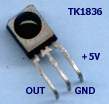
Once again, we start from the LED flasher circuit from our previous articles in this mini-course; we are going to add an infrared receiver IC, a TSOP1836. This integrated circuit manufactured by Temic/Vishay is very simple to use, as its only three pins must connect to the positive power supply (+5V), negative (GND), and remote control decoder (OUT). The receiver's output connects to Nutchip's remote control decoder input, namely the REMOTE pin (pin 6). The manufacturer specifies a pull-up resistor to keep this output positive when no signal are received: the REMOTE input integrates this resistor therefore it is no longer necessary to add it externally.
The infrared
receiver IC
Our (infrared) remote controlled LED counts just 5 parts other than the Nutchip itself.
The breadbard we already shown inpart 1 can be adapted for this experiment with few minor changes. Be careful to not to reverese the infrared receiver while inserting it to the breadboard. This IC looks like a transistor with flat faces, except the one carrying the black lens for the infrared receiver. This is the sensitive side which captures the infrared stream coming from remote controls, and must always face up.
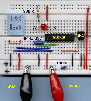
Parts list
- DL1: red LED diode
- R1: 390 ohm resistor
- OSC1: 3-pin, 4 MHz creamic resonator
- C1: 100 nF ceramic capacitor
- IR1: TK1836 or TSOP1836(Temic) infrared remote control receiver
- IC1: Nutchip NUT01-AK
You need also: an universal remote control (we recommend a Visa Simplex set to "Philips" mode), a 5Vdc regulated power supply, a solderless breadboard, Nutchip a programming interface with cable, assorted wire jumpers, and a PC running Nutstation.
L'azionamento START-STOP sulla basetta sperimentale
As you can expect, there are many infrared receivers on the market. You can usually replace one with another, provided they have the same power supply requirements and the same carrier frequency, 36 kHz in our case.
Remote control keys are written on truth table in the special "remote" column. Click on a cell from this column to select a remote control key, from none ("---") to any key from key1 to key8. If, for example, we select "key1" for a given state, then Nutchip will jump to the state specified as "next" every time the first remote control key is depressed.
The final truth table resembles closely the one we developed for the START/STOP drive. Just assume that the first remote control key (key1) works as the START button, and the second one (key2) as STOP.
STATE
OUTPUT
INPUT CONDITIONS
NEXT STATE
ST. 0
LED is OFF
(that is, OUT4 = 1)IF KEY1 IS DEPRESSED
JUMP TO STATE ST. 1
ST. 1
LED is ON
(that is, OUT4 = 0)IF KEY2 IS DEPRESSED
JUMP TO STATE ST. 0
Let's write down the truth table using Nutstation. After some mouse-clicking, you should get a table like this one:
Type the comments in you native language: in english they sound as "LED is off, press START key to switch it" and "LED is on, press STOP key to switch it.". Comment are useful in order to understand better how a table works, especially if you need to modify many month after creating it, or if people other than the designer should need to modify or understand it.
As all truth tables, st0 denotes the power-on state. This is the state the Nutchip assume when first powered on or after a black out.
Note: the table file is "start_stop_remote.nut". It is installed automatically by Nutstation, look in the folder "nutfiles". For more details about Nutstation click here.
Truth table do not differentiate among remote except by they number, from key1 to key6. But there are dozens different remote control types commonly available: how can a Nutchip know which key comes first and which one comes sixth? most remote controls accounts for a great deal of keys...
The easier solution is to usere a preset remote control, in our case an RC5-compliant TV remote control or the recommended Visa Simplex (tm) 6-keys remote control. The latter is of the "universal" kind, therefore quite easy to get. Nutstation handles both remotes, the only action required being the selection of the appropriate model from its remote control selection window.
From Nutstation's "Program chip" page, click on the remote control selection button to change remote control model. Nutstation stores automatically the remote control kind and remote control keys you enter, so you don't have to repeat this procedure every time a new project is created.
Once a particular kind of remote is selected, a pictures appears on screen showing the key correspondance .
The foolowing remote control types do not require you to specify exact codes:
- infrarred TV codes (uses program number selection keys)
- infrared TV Visa (uses all 6 keys, requires the remote to be preset as "Philips" mode)
- radio frequency (RF) codes
Alternately, you can make your custom remote control, specifying which key codes are required for any give key1...key8. To specify the codes, select:
- Curstom infrared
- Curstom radio frequency (RF)
And click any key to enter the codes, as detailed here.
This is your third prototype, so you should already know how to program a Nutchip with Nutstation. Select its "Program chip" page, and ensure that no errors are made from the message monitor panel: if any, correct them before attempting chip programming. Typical errors are non-existent state numbers, or states which are created but not used in any way.
If not already done, plug the interface to the bradboard and switch the 5V power on (be careful not to reverse power supply polarity!). Ensure the interface is connected to a PC serial port, the click on "Program Nutchip" button.
Just a few seconds to complete programming, and you are ready to test your new remote-controlled LED. Pressing key1 the LED lits, pressing key2 it shuts off. Easy, isn't it?This ends our 3-parts mini.course on Nutchip design. We hope you ejoyed it and want to experiment more: Nutchips are ideal for experiments, just change the table and reload the chip again and again, it is so convenient and fun!
If you want to see more design examples, we recommend you to continue with our design collection; or just go to site index for thorough infomation.