|
|
|
|
The analog comarator is normally disabled, and input IN4 works as any other logic input
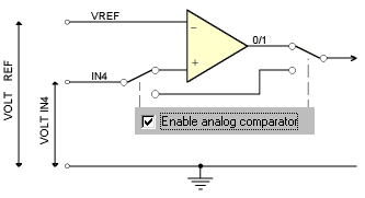
The analog comparator is connected internally to the IN4 input. Two electronic switches inside the Nutchip can be used to enable or disable the analog comparator block. If we want the analg comparator enabled, we must program the switching checking the "Enable analog comparator" option while programming the Nutchip using Nutstation.
- By default this checkbox is blank, causing the switches to be programmed in the position shown by the picture on the left. The analog comparator block is bypassed, therefore using the pin IN4 as a standard logic-level input.
The input IN4 is evaluated according to its logic level, exactly in the same way as the other inputs IN1, IN2, IN3. The pin VREF from the comparator block is not used and can be left unconnected.
By checking the "Enable analog comparator" option from Nutstation, the meaning of input IN4 changes. The internal switches connect the input pin to the "+" input of the analog comparator block, routing at the same time the relevant comparator output to the place previosly occupied by the input IN4. In practice, the analog comparator block takes the place of the previous digital input (see figure on the right).
This means that when considering the value of the input IN4 in our truth table, we refer to the result of the analog compare on the comparator pins (voltage applied to Vref and IN4 pins), in place of the bynary logic level on pin IN4 alone.
- We can connect pins Aref and IN4 to any voltage level in the range from 0 to +5V (hence the word "analog")
- Oppositely, digital inputs forbid a voltage in the range from +1.0 to +1.9V. Voltage levels from 0 to +1V are intrpreted as logic zeroes, and from +1.9V to +5V as ones (hence the word "digital").
An anlog comparator is an electronic circuit with two inputs and one output. The first input (marked '+') is the nutchip pin IN4. The other one, named the Voltage Reference (Vref, marked '-') goes to a dedicated pin. The output of an analog comparator is of the digital kind, and its binary value (either zero or one) depends solely from the difference between the voltage levels applied to its inputs. An analog comparator is suitable for detecting even very small differences on the input pins.

Checking the Enable comparator option, the output from the analog comparator block replaces IN4. The IN4 pin goes to one of the comparator's inputs.
- For a digital input standpoint, a voltage level of 2 volts is a bad choice. Subtle changes in the input level (e.g. because of interference or background noise) can cause it to oscillate from a logic leve zero to logic level one.
- For an anlogi input, oppositely, the same voltage level is an almost ideal condition! The threshold between 0 and 1 is precisely defined, and can be precisely set by the user varying the voltage on the Aref pin.
The analog comparator operate on digital voltages applied on its pins IN4 and Vref, but its output is a purely digital one. This is the digital value we refer to when filling the Nutchip truth table, and it takes the place of IN4.
The comparator compares the voltages on its inputs, regardless of the magnitude, and outputs a logic level accordingly. The output will be either zero if the voltage level on pin IN4 (+) is LESS than the voltage level on pin Vref(-), or one if the voltage level on pin IN4 (+) is GREATER than the voltage level on pin Vref(-).
Voltages on IN4 and Vref pins Result to be inserted in the truth table in place of IN4 Example VOLT IN4
greater than VOLT Vref1 Vref = 0,5V
Vin = 1,5VVOLT IN4
less than
VOLT Vref0 Vref = 3V
Vin = 1,5V
How to determine compare results. Note how the same input voltage, Vin=1.5V, can give a zero or an one depending on the reference voltage applied to the Vref pin.
The analog comparator input is suited to all the sensors that provide provide a variable voltage level in place of a digital output. Photocells, thermistors (temperature variable resistors), pressure transducers, potentiometers are a few examples. As a rule of thumb, we adopt an analog comparator in all those cases where the circuit is required to react to a precisely set voltage level.
The analog comparator must be enabled (if used) at the time of programming, checking the box from the Nutstation programming page. You need to do it once when creating a new table. The analog comparator enabling is saved in Nutstation truth tables, therefore you don't need to reset it thereafter or when loading one of the example truth tables supplied with Nutstation.
Building yourself a photocell is a practical (and fun!) way to get familiar woth the analog comparator. Try starting from the following schematic ( details here ).

An experimenter's phtocell