|
|
|
|
Differently form standard logic integrated circuits, a Nutchip truth table is not determined by the manufacturer. Instead, the user defines the relationships between inputs and outputs best suited to a particular application. A Nutchip's truth table binds four programmable inputs (IN1, IN2, IN3, IN4) to four programmable outputs (OUT1, OUT2, OUT3, OUT4). All you need to do to make a Nutchip to rise OUT1 when IN1 goes to zero is to write it in its truth table using your PC using our software, Nutstation . This software provides also a single-click download procedure which transfers the truth table from the PC to Nutchip internal memory (using this serial port interface). Once in the chip, the truth table actually makes the output pins switching according to input changes - at least until you decide to replace it with a new one!
The inputs IN1...IN4 are digital inputs. This means the are designed to work with signals assuming only two levels, about 0 volts and 5 volts.
A digital input is said to be:
- standing at logic level zero (low) if we connect it to a voltage less than 1 volt
- standing at logic level one (high) if we connect it to a voltage greater than 1.9 volts
- a digital input is not designed for connection to voltage sources between 1 and 1.9 volts. This event should be avoided as the logic level is undefined, meaning that the logic value is unpredictable and can zero as well as one.
Nutchip inputs are supplied with an embedded pullup resistor. This internal high-value (typically between 30 and 100 kiloohms)resitor makes the input automatically positive, if not connected externally to another voltage source that changes it. This internal resistor allows the input pin to be connected to any logic level output without problems, while at the same time allows an unused Nutchip input to be left disconnected without the need to "park" it to the positive power.
Note that there is an additional 4 factory preset inputs, to modify the behaviour of the chip, overriding the truth table rules.
Input IN4 defaults to a digital input, but if your application needs it, it can work also in analog mode, a mode that allows to see if an arbitrary threshold voltage has been surpassed or not.
A nutchip features four indipendent digital outputs. The outputs are of the push-pull kind, this means that a Nutchip output can sink current as well as sourcing it.
- We source current when the output is set to logic one. This schematic shows how to light a LED supplying a positive current. In this configuration you can draw up to 10 mA from a Nutchip output.
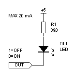
- We sink current when the output is set to logic zero. This schematic shows how to light a LED sinking current (the positive supply is actually sourcing that current). We usually talk about a negative or inwards current for the pin. The Nutchip can sink up to 20 mA per pin.

LEDs aside, a Nutchip output can be connected to a variety of circuits, as to any type of 5-volt digital integrated circuit inputs, a relay driver, a buzzer driver, optocouplers, and many other loads. Se our projects archive for good examples.
Using a Nutchip is like having lots of integrated circuits. We can implement all those logic functions that are not standard, saving the many ICs usually required to build them form standard parts. This is only the beginning: every Nutchip includes not only a programmable logic, but it complements it with a remote control decoder, a timer, and an analog comparator!