HGF AND REMOTE THERMOSTAT:
A COMPREHENSIVE APPROACH
The Head Gasket Failure (HGF) on the Rover K 1.8 is a well known problem, affecting mostly MG-F but also several other cars sharing the same engine, including the Lotus Elise and the Land Rover Freelander. HGF might be originated by many causes and some have already been explained and demonstrated (bad maintenance, excessive/incorrect work to head, wrong gasket materials/design, bad liner/block alignment, thermal shock, oil temperature, etc.). The Rover gasket for the K has been improved over the years and this has already reduced the HGF significantly, but some HGF still occur. Although the Rover K HGF is certainly a problem in modern automotive reliability standards, it has to be made clear HGF is far from being a probable event on any K powered car.
A common approach for the Lotus community has been pointing at the length of pipes between the radiator (at the front of the car) and the engine/thermostat (at the back) as a major cause of HGF due to cyclic thermal shock suffered from the engine. Also the position of the thermostat (on the return path from the radiator) has raised some criticism. This page is an attempt to prove this is not true.
To prevent HGF some companies in the recent past have brought out a modified cooling circuit using a remote thermostat, while recently MG Rover itself has developed a new cooling system for the K, implementing it thoroughly in the production line, from MG-TF to Land Rover K engines. Rover hasn't actually admitted the original cooling system was somehow flawed, but the efforts they put on a substantially new system should at least prove there was some margin of improvement…
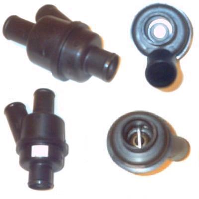
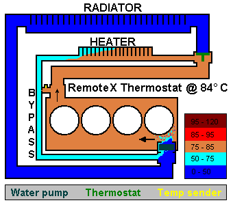
The lack of information coming from Rover about the whole matter has generated a lot of talk about the nature of the problem, its dimensions and the possible solutions. Lots of people with different level of knowledge have brought in their opinion and experience. Some genuinely trying to help with no other interest, some other also with some commercial support. As things seemed a bit confused to me, I first decided to get hold of a remote thermostat (picture below) to understand its working principles. My intention was to fit it on my Elise S1 at the next coolant change. Unfortunately getting hold of the correct hoses and pipes has proven to be a bit more difficult than expected. Further investigation has also shown the black remote thermostat has actually been thoroughly used on Rover diesel engines in the last decade.
An effective way of sourcing all the key components for the fitting is through Land Rover dealers: the kit PCH00190 is designed to fit the K powered LR Freelander, but it will suit the Elise with minor modifications.

In these pages I will try to explain some basic principles on how a the cooling system should work, the different approaches brought by different people/companies and the technical reasons for those choices. In my attempt of keeping it simple and interesting I tried to avoid formulas and calculations, inserting some drawings instead.
A fitting guide for the above kit could be found Here.
Although not directly related to the Rover K engine, to give some comparison I also wrote some notes about the cooling system of a Cast Iron Block (CIB) generic engine.
any comment or question is much appreciated, please send it to: elise_s1@yahoo.com
The Rover K engine:
The main peculiarity of the cooling system is as stated in the engine workshop manual: The siting of the thermostat in the inlet, rather than the outlet side of the system provides a more stable control of the coolant temperature in the engine.
The obvious question is: why is the thermostat in the inlet when its classic site is on the outlet? The answer lies under the more stable control of the coolant temperature in the engine.
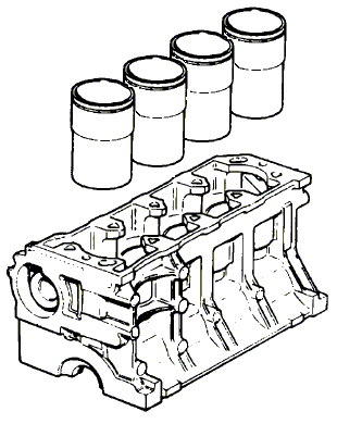
The Rover K is not a CIB engine: its design consists of 4 separate cast iron liners sandwiched between a light alloy head and a light alloy block. The whole engine is hold together with very long steel bolts, while coolant runs all around the liners (wet liners) within the alloy block.
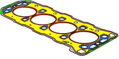
The head gasket has the dual purpose of sealing the coolant flow from the combustion chamber (between the head and each liner) and sealing the coolant flow from the oil passageways and from the outside (between the head and engine block). Basically 5 different pieces made of 2 different materials have to be perfectly mated to a single piece head with a single gasket in between.
There are many advantages in this setup compared to a single piece CIB engine (weight saving, very good liner heat transfer, easier block casting, easier bore modularity, etc.) but there is also a well known negative aspect: inside the engine the temperature has to stay within strict limits and, more importantly, the temperature has to change slowly and evenly. This is mostly because of the materials used for the engine block, cylinder liners and engine bolts. Aluminum and iron alloys have very different heat capacity, thermal conductivity and thermal expansion coefficient. Obviously the expansion coefficient is important because the liners and the block will not keep the same height at different temperatures. Heat capacity and thermal conductivity are also relevant, as the two materials will change their temperature (hence dimensions) at different speed once placed in the same coolant flow. Another relevant aspect of this setup (and a great difference from a CIB) is the relative mechanical weakness of the block/liner assembly: although it is not a negative aspect in itself (allowing each liner to move and adapt Independently from the others), it certainly transfers some extra mechanical stress to the head.
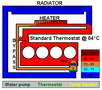
Now it should be clear the reason Rover had to fit the thermostat in the engine inlet: to keep the engine block/liner/head assembly within the tolerances of this specific design. It is no coincidence other big engine manifacturers who share the same "Open Deck" setup ("wet" iron liners and light alloy block) also have the thermostat on the way back from the radiator. Another positive aspect of this setup is about the engine positioning: no matter how long is the cooling circuit (short, as on a front engined car or long, as on a mid engined car) the thermostat will deal with it in the same way.
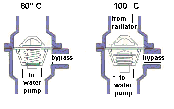
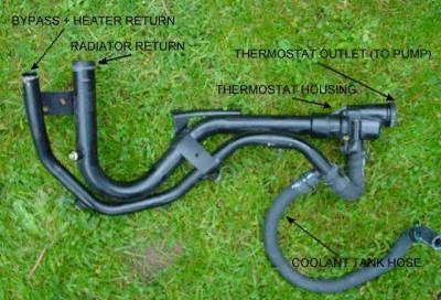
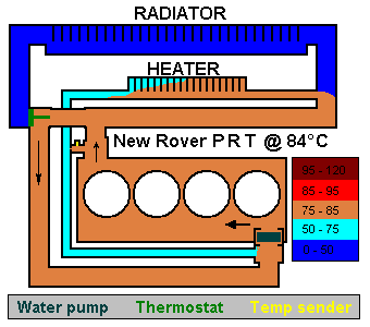
The thermostat on the K benefits from no help from the coolant held inside the engine and relies only on the bypass flow to blend the incoming coolant. Although this could be a stressing setup for the thermostat (as the bypass and radiator flow join each other right at the bulb), experience on the smaller units (The Rover K takes full advantage of the modularity allowed by its design, being available in 1.1,1.4, 1.6 and 1.8 litres) has proven a certain reliability. In the picture below it is shown the actual piping as fitted on all standard K engine.
The big one
Now let’s look at the Rover K 1.8: it shares most of the parts with the smaller brothers, including thermostat, bypass circuit and coolant pump. What is different is obviously the extra heat generated. The common approach to treat the extra heat is to fit a bigger radiator providing cooler fluid returning to the engine. As the radiator is dimensioned keeping the worst conditions in mind (maximum heat generated by the engine and minimum heat transfer to air), the radiator is overcooling the fluid in most cases.
With this setup the system starts to behave differently: as the thermostat housing is balanced to sense immediately both the bypass and the radiator flow, if the latter is sensibly colder the thermostat will not work as in the smaller engines.
This could lead to two possible issues:
The misbehaviour of the thermostat has some consequences:
It has to be noticed both problems a. and b. could eventually lead to HGF on the K, while they are not an issue on a CIB engine. On the other side, the K does rarely suffer from global overheating.
Prior to the list of the possible solutions, it needs to be specified the use of the engine: on a race oriented engine the chance of a HGF after 15.000 miles is nothing to worry about (as an engine rebuild including HG change will be scheduled way before it), while on a standard engine expectations of a faultless operating life could extend up to ten times this mileage!
Worth mentioning is also the fact that none of the solutions listed below has proven evidence of being an improvement over the standard system to prevent HGF: there is no modification achieving a sample of some significance (there are not enough engines with a different thermostat running at least 100k miles without being rebuilt). Only the Rover remote thermostat may give a big enough sample (being factory fitted) in the next years.
The drilled thermostat
A common attempt to improve things is to drill one or more small holes in the original thermostat outer ring to allow a small flow through even when closed. As it works as a small extra bypass it does reduce the dynamic issue, while the thermostat will adjust to maintain the static issue as is. It also needs to be said that the drilled thermostat does increase a little the flow with the stat closed (which is good) but it also cools the bulb, keeping the thermostat closed for much longer (which is very bad).
The 82° thermostat
Another approach has led to the fitting of a new thermostat with a different, colder, opening point. As the balance between the radiator and the bypass flow doesn't change, the dynamic issue is not solved (although the cycling will take place at lower temp), while the static issue is effectively corrected. Negative point is also the absence of control over any flow temperature above the one keeping the thermostat open, leading to variable operating temperature. The 82° thermostat is part of the 190 bhp upgrade for the VHPD engine.
The X remote thermostat
Under this description fall some devices who shares the same principles, although different in shape and plumbing. They are originated from a completely inverted approach: If the original cooling system is no good, let use a cooling system which has proven to be very effective on other engines. This system follows the lines of the remote thermostat as fitted on CIB engines. Unfortunately the problems on the K are of different nature (as explained above).
Fitting the thermostat on the engine outlet could solve the thermostat dynamic issue (because of the blending/dampening effect of the coolant inside the engine and the engine itself) and the static issue (as the coolant temperature at the engine outlet is higher compared to the inlet). The thermostat will work beautifully and also the temperature measured by the senders at the engine outlet should be stable. Sadly all the control over the flow temperature at the engine inlet is gone and any level of gradient and temperature fluctuation is allowed inside the engine, as long as the final temp is constant. Although this setup can't possibly prevent HGF in the long run, the risk of temporary overheating as described in c. is sensibly reduced.
The Rover Pressure Relief Remote Thermostat (PRRT)
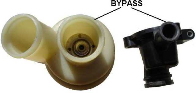
The new MG Rover thermostat seems to be the result of a comprehensive re-work of the cooling system on the K. Although keeping the original layout (thermostat on the return path from the radiator, bulb in the bypass flow when closed) its design is improved in all aspects. The picture below shows the enormous difference in the bypass size between the PRRT and the original thermostat housing.
The key to understand the advantage of this setup is in its own description: Pressure Relief. On all the previously described setups there is always a relatively high pressure difference between engine coolant inlet and outlet, especially with the thermostat partially closed. This is because the water pump (placed right at the engine inlet) does struggle to "suck" the coolant through small and long pipes while at the engine outlet the same small and long pipes do reduce the outgoing coolant flow. As the water pump purpose should be to supply flow and not pressure, some of its work is just wasted into cavitation. The main advantage of the new Rover setup is its capability of converting the pressure difference into coolant flow.
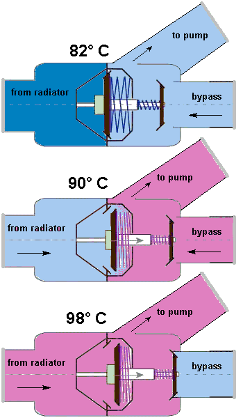
Both static and dynamic issues are eradicated by the short, very high flow bypass. The big bypass also ensure a much higher flow and lower pressure when the thermostat is closed (see 82°C picture), eliminating problem a. at any temperature.
With the thermostat open (90°C picture) the bypass will still flow most of the coolant, keeping higher flow and level temperature both at the thermostat bulb and, more importantly, inside the engine.
As the big bypass could end up "robbing" part of the flow originally running through the radiator, the PRRT does close its bypass if the temperature at the bulb gets too high (98°C picture), ensuring the best possible cooling power. High pressure peaks in the circuit are still prevented, as the bypass is kept closed by a low load coil spring.
The distance of the PRRT from the pump also allows a full blending between the bypass and radiator flows. A positive side effect of the PRRT constantly high coolant flow is to be found if an oil/water heat exchanger is fitted on the main circuit, assuring the maximum heat transfer regardless of coolant temperature. Also worth mentioning, on the Lotus Elise, the possibility to close the heater circuit with a valve (very useful during the hot summer months) without significantly reducing the overall bypass flow.
Fitting Guide Alternative setups
You are visitor number:
![]()