|
|
Thesis in Electronics Engineering (DU) on ADSL system with DMT modulation in respect of the Standard ANSI T1.413 |
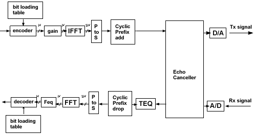
Basic implementation Figure 3 shows a
block diagram of a basic DMT transmitter.
The key element of
the DMT implementation is the FFT/IFFT. IFFT is
an elegant and efficient way to create a sum of N
carriers each modulated by its own phase and
amplitude. Since we implement a baseband line
code, we artificially duplicate each carrier with
its conjugate counterpart at a high frequency to
generate an IFFT output that is real only,
holding 2N time domain samples. This vector is
applied using a digital to analog converter to
the line. The input to the IFFT module is a
vector of QAM constellation points - N complex
numbers, defining the amplitude and phase of each
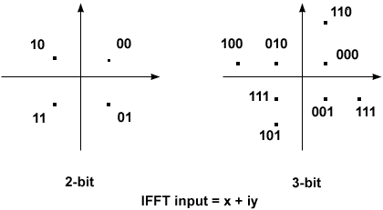
carrier. Figure 4 shows an example of 2 and 3 bit
constellation according to the ADSL standard.
Figure 5 shows a detailed description of a DMT modem.
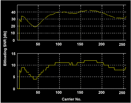
Encoder/ decoder As was described before the encoder takes the data bit stream and encodes it into N QAM constellation points. This encoding is done according to the bit loading table which defines the number of bits carried by each tone. Clearly high SNR (Signal to Noise Ratio) carriers can carry more bits than low SNR carriers so the bit loading table reflects the variation of the SNR over frequency. Figure 6 shows typical example of SNR and bit loading. The bit loading
table is calculated during startup according to
the actual measured SNR to allow optimal use of
channel capacity. Loading is limited by the ADSL
standard to 2-15 bits per tone. When we want to
serve the customer with a specific bit rate, we
allocate the bits to the carriers in such a way
that the sum of all the bits on all carriers
matches the desired rate, and the probability of
error on each carrier is about the same. When we
want to give each customer the maximal available
bit rate, we allocate to each carrier the maximum
number of bits that we can transmit without
errors, based on the measured SNR of that
carrier. This latter mode is usually referred as
the rate-adaptive mode. This way a customer
living close to the exchange will have a high SNR
and high data rate, whereas a customer living far
from the exchange will suffer from more line
attenuation and less bits shall be allocated on
each of the carriers.
Gain The gain stage implements the following functions: - Normalizing all constellations to a constant unit energy. Note that high loading constellation has higher energy, see figure 6. - Compensation of analog front end (AFE) frequency response. - Fine equalization of BER among the different channels by gain adjustment. IFFT / FFT This module was previously described. Cyclic Prefix add/drop Each symbol has a cyclic prefix that is 1/16 symbols length. This CP separates the symbols in time in order to decrease intersymbol interference (ISI). As is well known, the signal going through the line is linearly convolved with the impulse response of the line. If the impulse response is shorter than the duration of the cyclic prefix, each symbol can be processed separately, and there is no intersymbol interference (ISI). Also, in this case the receiver views the incoming signal as if it has gone through a cyclic convolution. This matches the FFT processing very well and ensures orthogonality between carriers. Echo cancellation This module is described below. Time equalizer -- TEQ Time equalizer is
a linear filter designed to minimize the
intersymbol interference (ISI) and interchannel
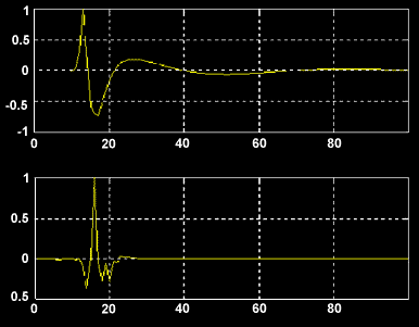
interference (ICI). This is done by shrinking the
total impulse response of line to the length of
the cyclic prefix -- see figure 7. In that way
one symbol can not interfere with the next one so
ISI is eliminated.
Figure
7: TEQ Influence over Impulse Response
1 |
2 | 3
|
© 1999 diritti riservati


