
Reinier van Kleij (1) and Willem F. Bronsvoort
Faculty of Technical Mathematics and Informatics
Delft University of Technology
Julianalaan 132
2628 BL Delft
The Netherlands
Abstract
Direct display algorithms display a CSG model without first converting the model into a boundary representation. Three such algorithms are described. All three are based on the scanline display algorithm, and are able to handle both polygonal and quadratic faces.
The first algorithm is based on Atherton's recursive subdivision scanline algorithm, the second is a combination of a scanline and a ray casting algorithm, and the third is a scanline version of the Trickle algorithm. A multiprocessor system in which these algorithms can be incorporated is also described.
The performances of the algorithms are compared. It turns out that the algorithms efficiently display CSG models on general-purpose architectures. Also a comparison is made between the performances for polygon-approximated models and exact models for objects bounded by quadratic faces, such as spherical, cylindrical and conical faces, to get an indication of how many polygons can at most be used to approximate quadratic faces and still have better performance.
Keywords
graphics performance, display algorithms, scanline algorithms, parallel algorithms, solid modelling, CSG models, polygonal and exact models
(1) Present address: L'Unione Sarda, Via Regina Elena 14, 09124 Cagliari, Italy
1. Introduction
Constructive Solid Geometry (CSG) has become a dominant representation scheme for solid modelling. Objects are represented in a CSG model as a set combination of transformed primitive objects, such as cube, cylinder, cone and sphere. The primitives can either be bounded by polygonal faces only, so that curved faces have to be approximated, or be bounded by polygonal and higher-order faces, in particular quadratic faces such as spherical, cylindrical and conical faces.
There are two alternative ways to display a CSG model (Bronsvoort 1988). The first is to derive a complete boundary representation from the CSG model using a boundary evaluation algorithm, and then to apply a standard display algorithm (Foley et al 1990) to the computed boundary representation. The second is to use a CSG direct display algorithm, which classifies a restricted number of points on the boundaries of the primitives against the CSG tree to determine the visible parts of the composite object.
Several direct display algorithms for CSG models have been developed during the last decade (eg Roth 1982; Atherton 1983; Rossignac and Requicha 1986). We have implemented three direct display algorithms that are all based on the scanline algorithm and can handle both polygonal and quadratic faces. The algorithms are: an adapted version of the recursive subdivision scanline algorithm for polygonal primitives of Atherton (1983); the algorithm of Chung (1984), which is a combination of a scanline algorithm and a ray casting algorithm; and a scanline version of the Trickle algorithm, a CSG depth-buffer algorithm (Epstein et al 1989; Rossignac and Wu 1992).
This paper has four goals:
1) Compare the performance of the three algorithms wrt CPU times for a number of realistic test models.
2) Provide an experimentally based evaluation of the relative merits of polygonal and exact models.
3) Give insight into the efficiency of parallel scanline algorithms.
4) Speculate on future performance of scanline algorithms for CSG models on general-purpose workstations and multiprocessor systems.
In Section 2 the concept of CSG and the display of CSG models are discussed; also the test models are introduced. In Section 3 the basic scanline algorithm is described. In the next three sections the CSG scanline algorithms that are compared, are described: in Section 4 the recursive subdivision algorithm, in Section 5 Chung's algorithm, and in Section 6 the Trickle algorithm. Measurements for the algorithms are given in Section 7. In Section 8 the multiprocessor system into which these algorithms can be incorporated is described, and some results are given. In Section 9 the results of the previous sections are reviewed, and conclusions are drawn; finally some speculations on future performances of the algorithms are made.
2. Constructive Solid Geometry models and their display
Constructive Solid Geometry (CSG) is a powerful technique for modelling complex mechanical parts (Requicha 1980). With CSG, simple parametrized objects, called primitives, are positioned in space and dimensioned using the geometric transformations translation, rotation, scaling and skewing. By applying the binary, volumetric set operations union ([[union]]), intersection ([[intersection]]) and difference (-), the primitives are combined into more complex, composite objects, to which the set operations can be applied again. The set operations are stored in the nodes of the so-called CSG tree; references to the primitives are stored in the leaves; the root node represents the complete composite object.
The primitives can be represented by the equations of its faces, each of which divides space into two halfspaces, one on each side of the face. A primitive is then the intersection of some of such halfspaces. For example, a cube can be defined as the intersection of six halfspaces, each defined by a plane. An alternative is to represent each primitive by its faces and a point-inclusion procedure.
Well-known direct display algorithms for CSG are the ray casting algorithm (Roth 1982), the scanline algorithm (Atherton 1983) and the depth-buffer algorithm (Rossignac and Requicha 1986). Although the ray casting algorithm gives good image quality, it is computationally expensive. The depth-buffer algorithm is only feasible using special-purpose hardware. Atherton's algorithm gives reasonable display times on a general-purpose workstation. Its drawback is the use of polygonal primitives, and although curved faces can be made to look smooth by Gouraud or Phong shading (Foley et al 1990), their silhouettes and intersection curves still look jagged. This effect can be reduced by using many polygons for approximation, but that leads to a considerable increase in computing time and memory requirements.
It is therefore worthwhile to look for CSG scanline-oriented display algorithms that use quadratic faces directly. All algorithms developed are based on the standard scanline algorithm, and they differ mainly in the way the visible face points on the scanline are determined. The first algorithm subdivides the scanplane sections, ie the intersection curves of the scanplane and the primitives, into monotonic pieces as described by Pueyo and Mendoza (1987), and recursively sorts, classifies and subdivides monotonic pieces until a visible piece is found (van Kleij and Roussou 1991; van Kleij 1992, 1993). The second algorithm, which is based on (Chung 1984), uses a combination of a scanline approach and a ray casting approach, and sorts and classifies the faces at each pixel. The third algorithm is a scanline version of the Trickle algorithm (Epstein et al 1989; Rossignac and Wu 1992), originally a depth-buffer algorithm for special-purpose hardware.
All algorithms described are embedded in the CSG solid modelling system Quamo (QUAdric MOdeller) developed at Delft University of Technology (van Kleij 1990). Quamo is written in C and runs on an HP 9000 Series 400 with a Motorola 68030 CPU and 16 Mb RAM under the HP-UX operating system. For display, an X-window of 512 x 512 pixels with 8 bits per pixel is used. CPU times for single-processor versions given in this paper were measured in this environment.
To compare the efficiency of the display algorithms, we have chosen four characteristic CSG models of industrial settings (see Figures 1-4). The performance of a display algorithm for a particular image of a model, heavily depends on complexity factors intrinsic to the model and view-dependent factors. Some intrinsic complexity factors are (see Table 1):
* the number of quadratic faces and polygons
* the number of pairs of intersecting primitives
* the number of set operators of each type.

Table 1 Values of intrinsic complexity factors of the test models.
Other possible model complexity factors, such as the number of holes in the model, the number of faces of primitives not on the boundary of the composite object, and the order of the intersection curves (first order, quadratic, quartic), are related to the intrinsic factors. Some of view-dependent factors are (see Table 2):
* the number of pairs of overlapping primitives on the screen: many overlapping primitives increase the depth complexity of the image, ie the number of primitives that are behind each other
* the average number of pixels of the areas of overlap of primitives
* the average size of the primitives in pixels
* the number of pixels that the model covers.

Table 2 Values of view-dependent complexity factors of the test images.
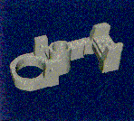 Figure 1 MBB Gehäuse.
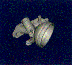 Figure 2 Carburettor.
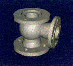 Figure 3 Valve.
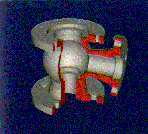 Figure 4 Cutaway Valve.
The exact relations between these factors and the performances of the display algorithms, might be established by a theoretical analysis of the complexity of the algorithms, or by a statistical analysis of measurements involving hundreds of realistic test models. This would result in expressions for the complexity of the algorithms in terms of the factors. We have not pursued this approach, first, because the algorithms are too complex for a detailed theoretical analysis, second, because hundreds of realistic test models are not available to us, and, third, because if mathematical expressions were obtained, it would be doubtful whether these would give much insight into the practical behaviour of the algorithms. We will therefore pursue an experimental approach by giving results of measurements, and explanations for trends in these results, which together give an indication of the performance of the algorithms in general.
Quamo has the ability to use either an exact or a polygon-approximated representation for quadratic faces. The accuracy of the approximation is controlled by the resolution: with resolution n, a cylindrical face is approximated with n rectangles, a conical face is approximated with n triangles, and a spherical face is approximated with ((n/2) - 2) * n rectangles and 2*n triangles. We have measured the performance of the display algorithms with exact models and with polygonal models with resolutions 4, 8, 12, 16, 20, 24, 28 and 32 (see Table 3 for the number of polygons for the test models at these resolutions). This allows us not only to compare the relative performances of the display algorithms, but also to get insight into the extent to which the use of quadratic faces is more efficient in terms of performance than the use of polygons. We define the resolution for which an algorithm displays a polygonal model as fast as an exact model, as the break-even point of the algorithm. For display of the polygonal models we used flat schading.

Table 3 Number of polygons in the test models with different resolutions.
3. Basic scanline algorithm
The standard scanline algorithm for displaying polyhedral models (Foley et al 1990) consists of two parts: a preprocessing part and a display part. In the preprocessing part, the objects in the model are transformed from world space to image space (see Figure 5a), and their edges are sorted on minimal Y-value into edge buckets. An edge bucket is a linked list of edges that occur for the first time at the scanline the bucket belongs to (see Figure 5b). The display part draws the image in scanline order, from the bottom of the screen to the top. A scanline is drawn from left to right. Two important data structures are used in the display part:
* the Active-Edge List (AEL): a list of all edges intersecting the current scanline, sorted on increasing X-value of the edges on the scanline (see Figure 5c); two adjacent edges determine a span (see Figure 5d)
* the Active-Face List (AFL): the list of all faces that overlap on the current span (see Figure 5e).
The AEL is updated when the next scanline is to be drawn: edges in the AEL that do not intersect the next scanline are removed from the list, the intersections of the remaining edges with the next scanline are computed incrementally, the AEL is sorted with a bubble sort, and finally edges in the bucket of the next scanline are merged into the AEL.
The AFL is updated at every edge in the AEL as a scanline is traversed from left to right: the face(s) left of the edge are removed from the list, and the face(s) right of the edge are inserted into the list. In the standard scanline algorithm for polyhedral objects, the faces in the AFL are sorted on depth in the scanplane (see Figure 5d), and the span is drawn with the colour of the nearest face. If intersecting faces are allowed, then the faces are sorted on both ends of the span. If the nearest faces found on both ends are different, then the intersection point of the scanplane and these faces is determined, the span is subdivided at that point, and the two new spans are handled recursively in the same way. The procedure that determines the visible face on a span is called the 'handlespan' procedure.
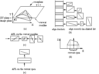
Figure 5 Objects and data structures in the standard scanline algorithm for polyhedral objects.
In the standard scanline algorithm, several types of coherence in the model and in the image are exploited:
* coherence between scanlines: edges that intersect one scanline, will mostly also intersect the next scanline, and the order of the X-coordinates of their intersection points with a scanline will change only gradually between scanlines; this is exploited by maintaining an AEL, and sorting it with a bubble sort
* coherence between spans: the collection of active faces will change only gradually as a scanline is traversed from left to right; this is exploited by maintaining an AFL
* coherence on a span: the order of the AFL, and thus the visible face, mostly remain the same; how this is exploited depends on the procedure that determines the visible face on a span.
To display models with quadratic faces, both the preprocessing part and the display part of the standard scanline algorithm need to be adjusted (van Kleij and Roussou 1991; van Kleij 1992, 1993). The preprocessing part must be able to transform quadratic faces from world space to image space. By computing the silhouette edges and sorting them into the edge buckets too, the possibilities that a quadratic face is active at the left of its edges, or that a quadratic face whose edges do not intersect the scanline is active, can be eliminated from consideration (see Figure 6a). The silhouette edges are defined as the curves consisting of the points for which the Z-component of the face normal is zero, and are calculated by intersecting the quadratic face with the polar plane of the quadratic face and the eye point (Blinn 1984). The plane-quadratic face intersection is computed by using the rotating-axis method (Albert 1949). The quadratic face is split into a front and a back face by the silhouette edges (see Figure 6b).

Figure 6 Silhouettes of a quadratic face.
Another problem is the fact that an edge bounding a quadratic face may intersect a scanline twice, which makes sorting the AEL more difficult (see Figure 7a). We therefore split the edge at the Y-extrema into monotonic pieces that intersect a scanline at most once (see Figure 7b), and sort these into the edge buckets.

Figure 7 Splitting an edge bounding a quadratic face.
The 'handlespan' procedure of the standard scanline algorithm for polygonal objects is inadequate to handle quadratic faces. For example, the fact that the nearest faces on both ends of a span are the same, no longer guarantees that these faces do not intersect, a property used by the procedure to draw spans in one operation for polygonal objects. So a different strategy has to be followed. Three effective strategies follow in the next sections. In these variants of 'handlespan', also classification of faces is incorporated to be able to display CSG models.
4. Recursive subdivision algorithm
The 'handlespan' procedure for Atherton's algorithm determines the visible face as follows: the faces in the AFL are sorted on increasing depth value at the left end of the span, and, starting from the first face in the AFL, the faces are classified against the CSG tree until either a face is classified as being on the boundary of the composite object, which is then the visible face at that point, or all faces in the AFL have been classified, in which case there is no visible face. So only the faces in front of and including the visible face are classified. The same is done at the right end of the span. If the depth order of the faces up to and including the visible face is equal on both ends of the span, the entire span can be drawn with the colour of the face visible on both ends. If the depth order is not the same, the intersection point of the first two different faces and the scanplane is computed. The span is then subdivided into two subspans, which are recursively handled by the 'handlespan' procedure. Bronsvoort (1986) gives a number of improvements on the CSG classification, which include pruning of the CSG tree, bottom-up classification with a status tree, and the notion that at the right side of the span the faces need only be sorted to detect intersecting faces.
The recursive subdivision algorithm discussed in this section, is a generalization for quadratic faces of the algorithm of Atherton (van Kleij and Roussou 1991; van Kleij 1992, 1993), and classifies on a span only the scanplane sections, ie the intersection curves of the scanplane and the primitives, up to and including the visible section of the composite object. This is in contrast to the scanline algorithm of Pueyo and Mendoza (1987), which performs a classification of all scanplane sections, before determining visibility using a scanline depth buffer.
A characteristic of quadratic faces that recursive subdivision must take account of, is that even in case of an equal order of faces on the span ends, intersection points can still occur (see Figure 8a). In this situation, intersection points must be calculated between every pair of faces in the AFL. This can be avoided by sorting the X-silhouettes into the edge buckets too. The X-silhouettes are defined as the curves consisting of the points whose X-component of the normal is zero, and are calculated by intersecting the quadratic face with the polar plane of the quadratic face and the point at infinity on the X-axis of the image space. The silhouettes introduced in Section 3 and the X-silhouettes subdivide the scanplane section of a quadratic face into monotonic pieces (see Figure 8b).
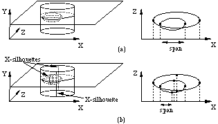
Figure 8 X-silhouettes and monotonic scanplane sections.
Monotonic scanplane sections have two important properties: first, if two faces have different depth order at both ends of a span, then there is exactly one intersection point; second, the depths of a monotonic face on both span ends form the bounding rectangle of the face on the span. We say that faces have depth overlap if their bounding rectangles overlap on a span. Two faces can only intersect if there is depth overlap (see Figure 9). To determine whether there are intersections, the depths of the faces at both ends of the span are computed, and only if depth overlap of two faces up to and including the visible face occurs (see Figure 9a, b), the two faces are tested for intersection points by the method described below. The intersection of two monotonic, quadratic faces can lead to two intersection points (see Figure 9a), so the recursive subdivision 'handlespan' procedure for quadratic faces needs to be able to handle two intersection points on a span.
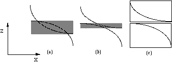
Figure 9 Depth overlap may indicate intersection points.
If two faces have equal depth order at both ends of the span and depth overlap on the span, then they need to be tested for intersection points. This is done by splitting the span into two subspans, and again testing whether the two faces have different depth order on both ends of a subspan (see Figure 10a). If they do, there is an intersection point on the left and right subspan, and the intersections are calculated with the procedure described below. If there is equal depth order, each subspan is tested for depth overlap of the faces. If there is depth overlap on a subspan, it is again subdivided, and the tests are repeated (see Figure 10b, c). This process continues until either there are intersection points in the subspan, or there is no depth overlap (see Figure 10d).
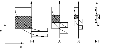
Figure 10 Testing for intersection points.
The intersection point of two faces with different depth orders on both ends of the span is calculated as follows. The smallest rectangle in which the intersection must lie is computed; this rectangle is the intersection of the two bounding rectangles of the faces on the span. The central point of this rectangle is the initial point for a Newton-Raphson iteration of the system of the two quadratic equations representing the intersecting faces (see Figure 11a). In most cases the iteration will converge to the intersection point in the rectangle within a few steps. However, sometimes the iteration diverges or converges to an intersection point outside the rectangle. In that case a new rectangle is determined by considering the depth order and the depth values of the two faces at the left end, in the middle and at the right end of the span to determine the span half to continue with, and the central point of the new rectangle is the initial point for a repeated iteration (see Figure 11b). This process is repeated until convergence is achieved, or the rectangle's width becomes smaller than a threshold value, which occurs rarely. In the latter case, the intersection point becomes the central point of the small rectangle. This procedure was found to be more reliable and more efficient than procedures based on analytical techniques.

Figure 11 Bounding rectangles for the calculation of intersection points.
Displaying complex CSG models like the carburettor in Figure 2, may lead to a large number of very small spans. Exploiting span coherence in that case might contribute little to the efficiency of the algorithm, since many spans are smaller than one pixel. In order to gain more from span coherence with complex models, a procedure for increasing the average length of spans has been developed, which gives about 10% improvement in performance (van Kleij and Roussou 1991; van Kleij 1992, 1993).
5. Chung algorithm
Chung (1984) describes a planar ray casting algorithm for displaying quadratic CSG models that has the scanline skeleton described in Section 3 as a basis. Unlike the standard CSG ray casting algorithm, which works in object space, the planar CSG ray casting algorithm works in image space. For every pixel on a span, the visible face is computed from the faces in the AFL by calculating the depths of the faces, sorting them, and classifying them using the CSG tree.
Chung (1984) states that the depths of the quadratic faces can be computed efficiently using the incremental method for generating points on an implicit curve described by Jordan et al (1973), but we found that computing the depths independently for each pixel using a square-root extraction is more efficient on contemporary CPU's. The Chung algorithm uses span coherence only for computing the depths of the faces, efficiently sorting the faces, and classifying the faces, but not for drawing several adjacent pixels in one step where the same face is visible.
6. Trickle algorithm
A CSG depth-buffer algorithm is an extension of the standard depth-buffer algorithm. Several such algorithms have been published, among others by Rossignac and Requicha (1986) and Goldfeather et al (1989), both of whose algorithms are meant to be implemented in special-purpose hardware. We have implemented a scanline version of the Trickle algorithm described by Epstein et al (1989) and Rossignac and Wu (1992), because it has shown to perform the best in comparison with other CSG depth-buffer algorithms.
Fundamental to the Trickle algorithm is the fact that the CSG tree can be rewritten as a sum of products. A product is the intersection of a number of positive and negative primitives. A primitive is negative if the path from the root of the tree to the primitive contains an uneven number of right branches from nodes containing a difference operator; otherwise the primitive is positive. To rewrite the CSG tree as a sum of products, it is first transformed into a positive tree. A positive tree is a CSG tree that contains only union and intersection operators, and the negative primitives are now complemented. The positive tree is created in the preprocessing part by a depth-first traversal of the CSG tree.
To display a scanline, the sum of products is generated by writing out the expression corresponding to the positive tree (Goldfeather et al 1989). Before doing this, superfluous branches are removed. For example, a branch consisting of the intersection of an active and an inactive primitive can be removed. This is done to avoid the excessively large number of products that may result if the CSG tree contains many intersection operators in nodes near the root of the positive tree.
The 'handlespan' procedure displays the sum of products by generating a depth buffer for each product in the sum to which the standard depth-buffer procedure is applied. It uses three pairs of buffers. Each face has buffers Z3 and I3, in which depths and intensities of the face are stored, when it is under consideration. The depths of a face need to be computed at most once for every span. The depths and intensities of a product are stored in Z2 and I2, and the depths and intensities of the sum of products are stored in Z1 and I1. All buffers are one-dimensional arrays with one entry for each pixel on the span.
A product is rendered as follows. The Z2 buffer is initialized with the depths values of the front faces of the positive primitives most distant from the eye point. This is called the initial tentative front. The visible face lies behind or on the tentative front, because points in front of the initial tentative front are not contained in the intersection of the positive primitives. Figure 12 shows an example of an initial tentative front.
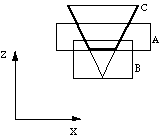
Figure 12 The thick line is the initial tentative front of the product AC.
After generating the initial tentative front, it is tested against the negative primitives in the product. The Z3 buffers of the front face and the back face of a negative primitive are filled, and if part of the tentative front is behind the front face and in front of the back face, then it is replaced by the back face of the negative primitive. If the tentative front changes, it needs to be retested against all other negative primitives in the product. In Figure 13a the initial tentative front is the front face of primitive B. The initial tentative front is tested against primitive A, leaving it unchanged (see Figure 13b). Then it is tested against primitive C, and part is replaced by the back face of C (see Figure 13c). Now, although the tentative front has been tested against all negative primitives, it is not correct: it must be retested against primitive A to get the correct result (see Figure 13d). After this intermediate tentative front has been generated, it is tested against the back faces of the positive primitives to assure that it is in the intersection of the positive primitives in the product: all parts of the tentative front that are behind the back face of a positive primitive, are removed, leaving a hole in the front. In this way only convex primitives are handled correctly, but this suffices for the quadratic faces like spherical, cylindrical and conical faces. If concave objects have to be handled too, the algorithm becomes more complicated (Epstein et al 1989; Rossignac and Wu 1992).

Figure 13 Generating the visible part of product B.
Some efficiency improvement techniques are used for displaying a span. Each product in the sum is pruned by computing the intersection rectangle of the orthogonal bounding rectangles of the positive primitives in the scanplane. If the intersection rectangle is empty, the product is discarded. Every negative primitive of which the bounding rectangle does not overlap the intersection rectangle, is removed from the product, because this negative primitive will never affect the tentative front. X-silhouette edges and other edges that are active, are used to compute the bounding rectangle of a primitive on the current scanline. The products are sorted on increasing minimum depth value of the intersection rectangle, so if the Z1 buffer is totally in front of the intersection rectangle of the next product, the procedure of generating the buffers Z2 and I2 for the remaining products can be stopped. In the buffers I1 and I2 no intensities are stored, but pointers to the faces from which the intensities result, and only after the final Z1 and I1 are determined, are the colours calculated from the pointers in I1. This considerably reduces the computational costs for quadratic faces. Edges of primitives that are not in any product, are removed from the AEL. The AFL need not be sorted, since it is only used to determine which faces of a primitive are active on the current span.
7. Performance
The computing times for the preprocessing of the test models are given in Table 4. The preprocessing is already more expensive for exact models without X-silhouettes, used by the Chung algorithm, than for low-resolution polygonal models, which is mainly due to the calculation of the silhouettes and the splitting of the quadratic edges. The break-even point lies between resolution 20 and 24. Since for recursive subdivision and Trickle the X-silhouettes need to be calculated too, preprocessing times for the exact models are about 30% higher and the break-even point lies between resolution 24 and 28.

Table 4 Preprocessing times for exact models without X-silhouettes,
exact models with X-
silhouettes, and polygonal models with different
resolutions.
Table 5 shows that Trickle is slightly faster than recursive subdivision. The Chung algorithm is on the average 30% slower than recursive subdivision and Trickle. Recursive subdivision as well as Trickle show a substantial performance degradation for the Cutaway Valve as compared to the Valve. For recursive subdivision the fact that the visible face is farther away, leads to more intersections, more span subdivisions and so more depth calculations and classifications. For Trickle it leads to more depth calculations and buffer merge operations. Chung, however, shows less performance decrease for the Cutaway Valve, because only few more depth calculations are done for the subtracted box, and classification time increases only slightly if the visible face is farther away.
From Table 5 and Table 6, it can be seen that the break-even point for recursive subdivision lies between resolution 16 and 20. The break-even point for Chung lies between resolutions 12 and 16. For Trickle the break-even point lies between resolution 4 and 8. This low break-even point is caused by the fact that the costs of the buffer manipulation per span are the same for polygonal as for exact models, whereas with polygonal models there are more spans. So Trickle is not efficient in polygon mode: recursive subdivision is about 30% faster. Trickle is, on the other hand, still faster than Chung for polygonal models with a resolution smaller than or equal to 20.

Table 5 Processing times of the recursive subdivision, Chung and Trickle
algorithm for exact
models.

Table 6 Average processing times of the recursive subdivision, Chung and
Trickle algorithm for
polygonal models with different resolutions.
8. A multiprocessor system for scanline display
In the previous section, it has been shown that the performance of contemporary general-purpose workstations is not sufficient to achieve interactive display times with CSG scanline algorithms. We have therefore developed a multiprocessor system based on such algorithms that displays the test models within a few seconds (van Kleij and Kuijper 1992). We have applied data decomposition, which means that every processor executes the scanline algorithm and computes a part of the image. Since the scanline algorithm exploits coherence on and between spans, the image is subdivided into horizontal strips, as is also suggested by other researchers (Sato et al 1985; Jansen 1988).
To equally distribute the work among the processors, a technique called interleaving is used. With interleaving, the scanlines are alternately distributed over the processors, eg processor 0 processes scanlines 0, N, 2N, ..., processor 1 processes scanlines 1, N+1, 2N+1, etc., where N is the number of processors. This scheme guarantees a good load balance, but it has the drawback that if the number of processors is large, the distance between the scanlines processed by one processor becomes large, and therefore the coherence between the scanlines is lost. A solution to this is to cluster the processors into groups, and let each group compute strips consisting of contiguous scanlines. The scanlines of a strip are then distributed among the processors in the group by interleaving.
A strip scheduling strategy is used to efficiently subdivide the screen into strips, and to distribute the strips among the groups of processors. The strips are dynamic, ie the number of scanlines in a strip depends on the workload of the strip. The strategy is based on task stealing (Holliman 1990). Initially the screen is subdivided into equally-sized strips. When a group of processors has finished its strip, it sends a request to the other groups to steal work from them; if there is a group that has a substantial amount of work still to do, it gives half of the remainder of its work to the requesting group.
In our system, a static data scheduling approach is used, which means that every processor contains the total geometric database; the compact geometric data base resulting from the use of exact representations of quadratic faces, and the memory size of the processors, still allowed us to display exact models containing up to 200 primitives. High-resolution polygonal models, however, cause problems. The use of static data scheduling implies that after a primitive has been preprocessed, the results need to be broadcast to all other processors. Before starting display, the CSG tree also needs to be broadcast to all processors.
The system has been implemented on a Parsytec MultiCluster-2 transputer system, which consists of three subsystems: the IO subsystem with a T800 with 4 Mb of memory, which is the host processor, and a GDS-2 graphics board, the processing subsystem with 16 T800's with 2 Mb of memory each, which are used for preprocessing and for display, and a programmable link switch to which all processors are connected. The system runs under Helios, a UNIX-like distributed operating system for multiprocessor systems. Quamo could be ported from HP to the transputer system, using the Helios C compiler, without major modifications, and runs on the host processor. The other processors, on which the display and scheduling processes run, are physically interconnected by a wrap-around mesh (Quinn 1987) to minimize communication distances to the host and the graphics board.
Each scanline algorithm discussed in the previous sections can be used for display in the multiprocessor system. We give results for the recursive subdivision algorithm only, as this algorithm is fast for both polygonal and exact models. The results of the two other algorithms will be comparable.
Tables 7 shows the total processing times for exact models and polygonal models with resolution 16. The total processing times include preprocessing and display times. To test the scalability of the multiprocessor system for exact models and for polygonal models with resolution 16, measurements were done for the test models with 1, 2, 4, 8 and 16 processors. The results are given Table 8; the efficiency is defined as
EN = . 100%
with T1 the total processing time on 1 processor and TN the total processing time on N processors.

Table 7 Total processing times for polygonal models with resolution 16 and exact models.

Table 8 Average total processing times and efficiency for polygonal
models with resolution 16
and for exact models, for several numbers of
processors.
It can be concluded that the efficiency decreases rapidly with an increasing number of processors for both exact and polygonal models, which is caused by the low performance of the Helios communication for the preprocessing results, the pixel colours and the strip scheduling requests. However, the efficiency decreases less with exact models than with polygonal models, because the geometric data base is much smaller using exact models. So the use of exact models results in a better scalable system.
9. Results and conclusions
We have described three scanline display algorithms for CSG models with quadratic faces: a recursive subdivision scanline algorithm, the algorithm of Chung, which is a combination of a scanline algorithm and a ray casting algorithm, and a scanline version of the Trickle algorithm, which is a CSG depth-buffer algorithm. Additionally, we have described a multiprocessor framework in which the three algorithms can be incorporated.
With regard to the complexity of the code, it can be concluded that the Chung algorithm is the simplest. The communication software needed in the multiprocessor system is rather complex, and it was quite difficult to get it running. The recursive subdivision algorithm, however, was easily ported to the system.
The results of the measurements are summarized in Table 9. For both the three single-processor algorithms and the recursive subdivision multiprocessor version, the average total processing time for quadratic and for polygonal models with resolution 16 are given. Polygonal models with resolution 16 result in reasonably accurate images, although the quality is still much lower than for exact models.

Table 9 Average total processing times for all algorithms for the
single-processor workstation and
the multiprocessor system.
For exact models, the Trickle algorithm is slightly faster than the recursive subdivision algorithm. For polygonal models, the recursive subdivision algorithm is fastest. Apparently, exploitation of span coherence in the recursive subdivision algorithm does pay off more for polygonal models than for exact models, which is caused by the complexity of intersection computations for quadratic faces. The Chung algorithm is slowest both for exact and polygonal models, because span coherence is least exploited in this algorithm. For more complex models, eg Cutaway Valve, where less coherence occurs, the performance of the Chung algorithm approaches the performance of the other algorithms. For very complex models containing hundreds of primitives, it might be faster. In an environment where both quadratic faces and polygon-approximated, higher-order faces are to be displayed, the recursive subdivision algorithm seems to be the best choice.
The differences in performance for exact and polygonal models are small, at least for resolution 16. In the previous sections it was shown that for the recursive subdivision algorithm the break-even point was between 16 and 20, for the Chung algorithm it was between 12 and 16, and for the Trickle algorithm between 4 and 8. So, as could be expected, low-resolution polygonal models result in better performances, whereas high-resolution polygonal models result in worse performances. The picture quality for the polygonal models can be improved by using Gouraud or Phong smooth shading, but this will increase the processing times considerably, and silhouette edges and, in particular, intersection curves will still look jagged. The break-even point, however, is lower than we expected, and so exact models are an attractive alternative for polygonal models, because they result in better image quality and smaller data-base sizes, at the cost of a slight increase in code complexity.
The multiprocessor system turns out to be 4-5 times faster than the single-processor recursive subdivision algorithm on the workstation. If, however, better communication facilities were available on the transputers, the scalability of the multiprocessor system would be much better, and thus the increase in display speed when using 16 processors.
A general conclusion is that display of CSG models with quadratic faces on general-purpose workstations in reasonable times is feasible with the algorithms described in this paper: both for handling CSG and for handling quadratic faces, efficient techniques are available. Contemporary single-processor RISC workstations that are a factor 10 faster than the workstation used here, can display the test models within a few seconds. On modern multiprocessor systems based on processors such as the Intel i860, a similar increase in speed might even result in display times in the order of tenths of seconds.
Acknowledgements
We are indebted to Ronald Roussou and Frido Kuijper for their contributions to the development of the algorithms described in this paper. We thank the reviewers for their valuable suggestions to improve this paper.
References
Albert A (1949) Solid analytic geometry. McGraw-Hill, New York.
Atherton PR (1983) A scan-line hidden surface removal procedure for constructive solid geometry. Computer Graphics 17(3): 73-82
Blinn JF (1984) The algebraic properties of homogeneous second order surfaces. Report Jet Propulsion Laboratory, Pasadena, USA
Bronsvoort WF (1986) Techniques for reducing Boolean evaluation time in CSG scan-line algorithms. Computer-Aided Design 18(10): 533-538
Bronsvoort WF (1988) Boundary evaluation and direct display of CSG models. Computer-Aided Design 20(7): 416-419
Chung WL (1984) A new method of view synthesis for solid modelling. In: Proceedings CAD84, Wexler J (ed), Butterworths, Guildford, UK, pp 470-480
Epstein DA, Jansen FW and Rossignac JR (1989) Z-buffer rendering from CSG: the Trickle algorithm. RC 15182, IBM Research Division, TJ Watson Research Centre, Yorktown Heights, USA
Foley JD, van Dam A, Feiner SK and Hughes JF (1990) Computer Graphics, Principles and Practice. (2nd edition), Addison-Wesley, Reading, USA
Goldfeather J, Molnar S, Turk G and Fuchs H (1989) Near real-time CSG rendering using tree normalization and geometric pruning. IEEE Computer Graphics and Applications 9(3): 20-28
Holliman NS (1990) Visualising solid models: an exercise in parallel programming. PhD thesis, School of Computer Studies and Mechanical Engineering, University of Leeds, Leeds, UK
Jansen FW (1988) CSG hidden surface algorithms for VLSI hardware systems. In: Advances in computer graphics hardware I, Straßer W (ed), Springer-Verlag, Berlin, Germany, pp 75-82
Jordan BW, Lennon WJ and Holm BD (1973) An improved algorithm for the generation of nonparametric curves. IEEE Transactions on Computers, C-22(12): 1052-1060
van Kleij R (1990) Implementation of a solid modelling system with quadratic surfaces. Report 90-41 Faculty of Technical Mathematics and Informatics, Delft University of Technology, Delft, The Netherlands
van Kleij R and Roussou R (1991) A CSG scanline algorithm for quadrics. In: Modeling in Computer Graphics, Kunii TL (ed), Springer-Verlag, Tokyo, Japan, pp 247-263
van Kleij R (1992) Efficient display of quadric CSG models. Computers in Industry 19(2): 201-211
van Kleij R and Kuijper F (1992) A multiprocessor system for displaying quadric CSG models. In: Proceedings CONPAR92 VAPP V Conference, 1-4 September, Lyon, France, Lecture Notes in Computer Science No. 634, Springer-Verlag, Berlin, Germany, pp 583-588
van Kleij R (1993) Display of solid models with quadratic surfaces. PhD Thesis, Delft University of Technology, Delft, The Netherlands
Pueyo X and Mendoza JC (1987) A new scan line algorithm for the rendering of CSG trees. In: Proceedings Eurographics'87, Maréchal G (ed), Elsevier Science Publishers, Amsterdam, The Netherlands, pp 347-361
Quinn MJ (1987) Designing efficient algorithms for parallel computers. McGraw-Hill, New York, USA
Requicha AAG (1980) Representations of rigid solids: theory, methods and systems. ACM Computing Surveys 12(4): 437-464
Rossignac JR and Requicha AAG (1986) Depth buffering display techniques for CSG. IEEE Computer Graphics & Applications 6(9): 29-39
Rossignac JR and Wu J (1992) Correct shading of regularized CSG solids using a depth-interval buffer. In: Advances in Computer Graphics Hardware V, Grimsdale and Kaufman (eds), Springer-Verlag, pp 117-138
Roth SD (1982) Ray casting for modeling solids. Computer Graphics and Image Processing 18(2): 109-144
Sato H, Ihsii M, Sato K, Ikesaka M, Ishihata H, Kakimoto M, Hirota K and Inoue K (1985) Fast image generation of constructive solid geometry using a cellular array processor. Computer Graphics 19(3): 95-102