|
|
|
|
|
Quick designs |
(aka "back of an envelope designs")It
surely happened to you, too. You are sitting with your friends, pleasantly
drinking and talking, when someone asks "Anybody knows how to...".
Immediate brainstorming, istantaneous urgence of a piece of paper to sketch something on. It usually ends up with a small, smart, useful circuit drawn on... the back of an envelope. |
|
in this section: |
|
Remote control tester / debugger
|
|||||||||
The simplest eeprom programmer...
|
|||||||||
...and the simplest RS232 monitor This clever circuit has
been posted on a newsgroup and Al Dickens kindly mailed it to me. At
first glance, monitoring the communication between two RS232 devices
(e.g. a PC and a peripheral) would require a separate PC with TWO free
serial ports.
|
|||||||||
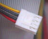
RS232 snakeNext time you stop to your favourite components store, don't forget to buy the following: 50 cm. 9 pole
flat cable Then snap all
connectors on to the flat cable (a small vice will do the job). You
get an instant male-male, male-female, female-female serial adaptor,
plus a short extender cord. A must-have tool if you're planning
to play with serial ports. You can even put an extra connector
for monitoring the RS232 traffic. |
|||||||||
Phone line status indicator
Note that this circuit is designed to work with italian telephones and that you need the written approval of your phone company prior to put something on the phone line. |

 A large number of RS232 devices "talks" half duplex.
Since only one device talks at any given time, a single port is more
than sufficient to monitor the full datastream.
A large number of RS232 devices "talks" half duplex.
Since only one device talks at any given time, a single port is more
than sufficient to monitor the full datastream. 
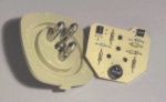
Almost free daily timerIf you don't have noticed it yet, I like to reuse hardware objects. This design brings new life to an old lcd alarm clock (but I bet it would work with LED types too). It is useful for a variety of purposes, from watering your flowers to (precisely) switch on the heating, the garden lights or even your christmas tree!
|
||
|
||
Appliance priority switchHere in Italy, the amount of mains power for most households is limited to 3 kW. With an hairdryer taking as much power as 1900W, I must check not to exceed the maximum power rating every time I switch on an electric appliance. Failing to do it may result in an unplanned walk out of the home, to restore the mains circuit breaker switch.
I use this
priority switch to automatically remove power from appliance B when
A is powered on. That is, A takes precedence over B, and
the maximum power consumption is never execeeded. |
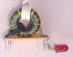
 This simple circuit
lights an LED when the connected circuit draws more than 3 A
ac. At 220 volts, this means something more than 600W.
This simple circuit
lights an LED when the connected circuit draws more than 3 A
ac. At 220 volts, this means something more than 600W. .
.
|
|
|