Vinicio Coletti's Web Site
Stepper motor controller for a telescope
It's many years that I own a very simple and relatively cheap newtonian telescope, the Konus Vega.
The main parabolic mirror has a diameter of 4.5" (114 mm) and its focal length is 35,4" (900 mm), giving
a luminosity ratio of about f/8. Eyepieces have a diameter of 0.8" (21,4 mm) and I have four of them, the
two sold with the telescope (Huygens type, focal of 6 and 20 mm), plus other two I bought later on
(a 25 mm Koellner and a 4 mm Orthoscopic). These latter eyepieces are much better than the original ones.
Since the magnification in telecopes is given by the ratio of the focal lenghts of the mirror and the
eyepiece, I can observe at magnifications of 36, 45, 150 and 225.
The mount is an equatorial one, but lacking motion and polar finder. There is the possibility to add
an AR motor, but it's out of production. Since I've been using this telescope only during summer and just
for short planetary and lunar visual observations, I didn't suffer too much the lack of motion.
But if you want to observe for a long time or at high magnifications, and generally for any serious
activity, you simply need the AR motion.
Last summer I tought I could build a motion system myself, based on a Microchip PIC16F84A microcontroller
and a low voltage stepper motor. I grabbed some used stepper motors and selected one with
relatively small angle/step ratio (7.5 degrees per step).

I connected 4 pins of the PIC to the bases of 4 NPN transistors, through 4 limiting resistors, to drive the
4 coils of the stepper motor. Then I have 4 buttons to control the motion and a two-colors LED to show the
status of the circuit. The R1-R4 base resistors, as well as the (optional) R5-R8 limiting resistors and the D1-D4 clamping diodes,
depend on the motor you are using and on the Q1-Q4 transistors you selected to drive them. All the rest is software...
About stepper motors
A stepper motor can be unipolar or bipolar. I will shortly cover here only the unipolar case, because
these motors are widely diffused and easier to drive. The motor has 4 coils, whose positive connections are all tied
togheter. We have thus normally 5 leads to deal with. If we connect to ground one of the coils, the motor does a
tiny rotation (7.5 degrees in my case, whilst others have 15 or more degrees). To move further the motor we must
disconnect the first coil from the ground, then connect the second one and so on for all 4 coils. Repeating this cycle
will produce a steady rotation.
One important thing we can deduce from this is that we can control very well the rotation speed. Also, since the
motor is always powered, it can mantain a steady postition even under mechanical charge. For the same reason, a stepper
motor delivers more power at lower rotation speeds. Moreover, there are no additional components to use if we want to
invert rotation, because we need simply to give pulses in reverse order.
If we call Coil 1 - Coil 4 the four coils of the motor, we can define 4 times:
Full stepping
| | Coil 1 | Coil 2 | Coil 3 | Coil 4 |
|---|
| time 1 | ON | off | off | off |
|---|
| time 2 | off | ON | off | off |
|---|
| time 3 | off | off | ON | off |
|---|
| time 4 | off | off | off | ON |
|---|
The above is called full step control because we make one step at each time. An alternative way
is called half step control, where we power also two adiacent coils at the same time, to move
the motor half-way. This implies a better control on position and speed, at the cost of doubling the
pulse ratio at any given speed.
Half stepping
| | Coil 1 | Coil 2 | Coil 3 | Coil 4 |
|---|
| time 1 | ON | off | off | off |
|---|
| time 2 | ON | ON | off | off |
|---|
| time 3 | off | ON | off | off |
|---|
| time 4 | off | ON | ON | off |
|---|
| time 5 | off | off | ON | off |
|---|
| time 6 | off | off | ON | ON |
|---|
| time 7 | off | off | off | ON |
|---|
| time 8 | ON | off | off | ON |
|---|
In my case I was able to obtain 3.75 degrees per half-step.
How it works
The goal of this projects were established to be:
- Three different basic speeds, to track the stars, the moon and the sun
- Fine tuning of all three speeds, with permament memory of the last stored value
- Quick motion to pass to another object, at different speeds
- Pause mode to momentarily stop the motion
- Reverse rotation, both at tracking and quick speeds
- Ease of use
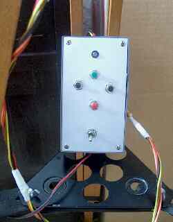 When the circuit is initially powered, the LED shows the basic tracking speed that was last selected:
RED for the Sun, YELLOW for the Moon
and GREEN for the Stars (I hope it is intuitive enough).
The LED is blinking slowly to signal that the tracking is not active (pause).
When the circuit is initially powered, the LED shows the basic tracking speed that was last selected:
RED for the Sun, YELLOW for the Moon
and GREEN for the Stars (I hope it is intuitive enough).
The LED is blinking slowly to signal that the tracking is not active (pause).
In this state we can press the right button to switch among the different speeds and the
left button to reverse the rotation. If we press the top button (green) the LED stops blinking
and glows steadily and the tracking begins. The bottom button (red) is used to save into memory the
current fine tuning for the selected basic speed.
During the tracking we can fine tune the rotation speed using the left and right buttons.
The top button stops the tracking, returning to the pause mode and the bottom button
activates the fast motion mode, with the LED blinking quickly.
During the fast motion mode (2x speed) we can use the right button to increase the speed (4x, 8x, 16x, 32x, 64x)
and the bottom button to return to normal tracking. Also, the left button reverse the fast rotation speed
(with about 1 second pause to stop the motor properly).
All commands are resumend in the following table:
| State | LED | Top button | Bottom button | Left button | Right button |
|---|
| Pause | Blinks slowly | Go to tracking | Stores current speed tuning |
Invert direction | Change basic speed (stars, moon, sun) |
|---|
| Tracking | Steady | Go to pause | Go to fast motion | Decrease speed |
Increase speed |
|---|
| Fast motion | Blinks quickly | Go to pause | Go to tracking |
Invert direction | Increase motion speed |
|---|
Results
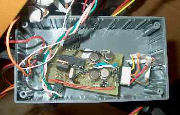 I realised this circuit on a standard multi-holes board (I lack its name...), I put it inside a nice plastic box,
with connectors for an external lead accumulator (12 V, 4 AH) and for the stepper motor. The accumulator
should be able to power the motor for about 12 hours, that is a night of continuous observation.
Since it works at 12 V it is also possibile to attach it to a car cigarette lighter or to an home power source.
I realised this circuit on a standard multi-holes board (I lack its name...), I put it inside a nice plastic box,
with connectors for an external lead accumulator (12 V, 4 AH) and for the stepper motor. The accumulator
should be able to power the motor for about 12 hours, that is a night of continuous observation.
Since it works at 12 V it is also possibile to attach it to a car cigarette lighter or to an home power source.
However, although the software works great, I cannot say I am totally satisfied by this project, because I faced two
main troubles: the lack of mechanical experience leaded to a far less than optimal motor-to-gear coupling and,
more importantly, the 3.75 degrees of motion was too much to yield a flawless tracking, with that particular
equatorial mount.
I could even see a star moving a bit in one direction than, ops!, go back to the start... A saw-tooth tracking,
isn't it? Well, I will have to increase the motor speed with a gear or use another motor with a different coupling.
But I am sure I will not change the software too much, because it was very easy and effective to use.
A different approach would consist in throwing away stepper motors and use a syncrhonous DC motor, with feedback
(close loop control).
Anyway I had confirmed in this occasion that I am more a software than an hardware bound animal...

Create your counter