|
At
this page I will introduce you to a type of display called Vacuum
Fluorescent Display (VFD).
This display is commonly used in VCR, stereos, carradio and
in other electronic equipment.
This type of display gives a bright light with great contrast.
Many people thinks this display is difficult to control, but no it
is NOT!
I will explain how you can re-use this display in your homebrewed
projects.
Background
A nice looking display always impress
and gives a nice light from your homebrewed project. I believe one
can always have the use of a display. Most common displays are LED
wich gives a bright light, but can most often only show numbers,
not character. Then we have the LCD type with backlight. This type
give not so nice impression and the contrast and light is not good.
The VFD-display is much better. They give a bright green light.
Almost every VCR use a VFD to show time and other info. Many home
stereos also use VFD. The latest trend is to have as much effect
as possible in thoose VFD. The bars and text are flashing and
running.
Many late evenings, I usually visit the local dump station for
electronic. There, I have found many VCR and broken stereos. All
of them had nice VFD. As you will see, the VFD display is custom
made for each purpose, so there is lot of preprinted text on the
VFD like "PLAY, REC, AM, FM, VCR, START, END......" and
there is also some digits. If you are lucky you find a VFD with
lots of digits. It is not difficult to get such a display working.
All you need is some power and a few circuits. Most often you will
find lots of pins connected to the glass of the VFD.
I will now go on explaining how they work, then how you can build
a unit to make the display come alive.
1. VFD
Operation
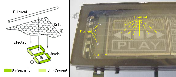
The
VFD is composed of three basic electrodes; the Cathode (Filaments),
Anodes (Phosphor) and Grids under a high vacuum condition in a
glass envelope.
The Cathode consists of fine tungsten wires which are coated by
alkaline earth metal oxides which emit electrons.
The Grids are a thin metal mesh which control and diffuse
electrons emitted from the Cathode.
The Anodes are conductive electrodes on which the phosphor is
printed to indicate characters, icons or symbols.
Electrons emitted from the Cathode are accelerated with positive
potential applied to both Grid and Anode, which upon collision
with the Anode excites the phosphor to emit light. The desired
illuminated patterns can be achieved by controlling the positive
or negative potentials on each Grid and Anode. This voltage can be
as low as 10VDC.
 1)Glass
Substrate (Anode Plate) 10)Getter 1)Glass
Substrate (Anode Plate) 10)Getter
2)Conductive
Layer
11)Face Glass (Cover Glass)
3)Anode
(Base)
12)Spacer Glass
4)Insulation
Layer
13)Evacuation Tube
5)Phosphor
(Display Pattern)
14)NESA (or ITO) coating
6)Conductive
Paste
15)Lead Pin
7)Grid
Mesh
16)Mold Resin
Basic VFD Structure
8)Conductive Frit Glass
17)Solder
9)Filament (cathode)
18)Frit Glass
Disassembled
VFD:
The
VFD is composed of a vacuum envelope with a front glass and the
base plate, in which cathode (filament), grid and anode are formed
as the basic electrodes
Cross
section of VFD :
Cross
section of VFD:
Filament
consists of tungsten coated with the oxidized Ba, Sr and Ca.
Powered filament generates heat and emits thermal electrons which
are dispersed and selected by the grid electrode and reach the
anode electrode. On the anode electrode, display pattern is formed
with phosphor which emit light.
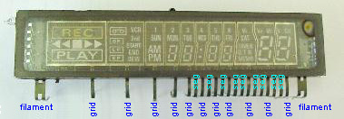
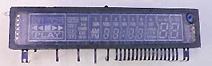
This
display is robbed from a VCR. The two large connection at each
side is the connection to the filament. The voltage over the
filament should be about 2-3V the current consumption is about
100mA. The display has 11 grids. Each of them has a connection out
from the glass substrate. The 9 rest pins are connection to the
segments in the display.
The controlling electronic will do like this:
First it will put the first grid to +14V and the rest to 0V and
apply +14V to the segment you want to be lighted in the first grid.
Then it will put the first grid to 0V and got to the next grid and
apply +14V. This scann will continue untill the last grid was
activated and the process will start all over again. The scanntime
is fast so you will not see that only one grid is activated at one
time. You will see them all shining.
If you want to test a VFD just connect 3V over the filament. Then
you apply +14V to one grid. the minus should be connected to the
filament. Now take a wire from the +14V and touch the segment pins
from the display except the filament, then you will burn it upp!
You will now see that the segment in the active grid will shine.
If you touch another grid nothing will happen, so don't worry.
How
to drive the filament
| AC Drive |
| Most popular method for
the audio system and large-size VFDs. |
[ Fig. 4 Connection of
AC Drive ] |
[Fig. 5 Potential of AC
Drive ] |
| DC Drive |
| Mainly used for small-size
VFDs driven by the car batteries. In this case, there are
differences in the grid and anode voltages at the ends of
the display pattern in the value of filament voltage,
which requires correction of the filament structure.
Therefore, DC drive is not available for large-size VFDs. |
[ Fig. 6 Connection of
DC Drive ] |
[ Fig. 7 Potential of
DC Drive ] |
| Pulse Drive |
| Used for relatively small
size VFDs which are driven by the car battery not by DC
drive. When setting the filament voltage, use the
instrument to measure the effective value to obtain the
optimum filament temperature. |
|