![]()
|
|
|
|
|
Nutchip truth tables |
Nutchips do not use a programming language. To make a Nutchip work for you, you fill a truth table with the input and output combinations required by your application. Let's see how.
Every logic integrated circuit (I.C.), as for example AND, OR, NAND and NOR gates, as well as FLIP-FLOPs, works according to a well-defined truth table. A truth table lilsts all of the values taken by the outputs (written a zeroes and ones), binding them to the values at each input pin.
| "NAND" TRUTH TABLE | ||
| IN1 | IN2 | OUT |
| 0 | 0 | 1 |
| 0 | 1 | 1 |
| 1 | 0 | 1 |
| 1 | 1 | 0 |
As an example, the last row of the NAND truth table (highlighted in yellow) states what follows:
- if both of the inputs (IN1, IN2) are high (1, a voltage near to the power supply level, typically more than 4 Volts)
- then the output (OUT) will be low (0, a voltage very low, typically less than 0.5 Volts)
A truth talbe lists each and every condition that could happen at the inputs: both inputs at zero, both inputs at one, first input at one while the second is at zero et vice-versa.
For each condition the table shows how the output will be, specifying if the output will be either high (1) or low (0).
With a few extensions, truth tables are well suited for describing the inner workings of most logic circuits. States are one of the most useful extension to truth tables, and are extensively used for describing flip-flops and all non-trivial logic circuits.
In fact, it is often the case that the same condition at the input gives different results (outputs) according to wich state the device is currently in. We can observe states in lots of everyday experiences, for example:
- the same input condition = toggling a switch
- gives two opposites results = light turns on or off
- according to the current state = light is currently off or on
In a state-based logic circuit, the outputs do not depend exclusively on the input conditions (as in the previous NAND example), but also on the current state of the device.
Therefore, to correctly describe a process like the toggling of a switch, we must specify the state while writing the truth table.
Here is how a truth table looks like after adding states:
|
LIGHTS SWITCH TRUTH TABLE
|
||
| CURRENT STATE (and OUTPUT) |
INPUT |
NEXT STATE |
| LIGHTS ARE OFF (OUTPUT= 0) |
TOGGLE | LIGHTS ON |
| UNCHANGED | LIGHTS OFF | |
| LIGHTS ARE ON (OUTPUT=1) |
TOGGLE | LIGHTS OFF |
| UNCHANGED | LIGHTS ON | |
Please note that the table shows the output in the same cell as current state. Most of practical logical circuits work well assuming that outputs will depend exclusively on the current state, therefore it is handy to group current state and current outpus together. Should it be necessary to change the outputs, then we will jump to a different state.It is not required that all states have different output patterns: it is perfectly valid to have two or more different states with the very same output values.
States appear in the last column too.This column specifies which state our logic circuit will assume as soon as each input condition becomes true.
|
Example: |
For every state-based logic circuit, it is very important to know which state is active at power-on. For example, we expect a well-designed counter to start counting from zero, not from a random number!
Logic circuit manufacturers always specify power-up states; additionally, they supply a reset pin that brings the circuit to a predefined state. This state is often referred to as reset state: and in Nutchip jargoon it is called the state zero (st00).
Like most digital logic ICs, Nutchips output are determined by the current state. Nutchips are state-based ICs. Each Nutchip provides four output pins; these pins can change only if the state changes.
Here it is a typical Nutchip truth table:
 This table implements a pathway lights timer. Lights are connected to the first output. A pushbutton is connected to first input. The system provides also a two-key remote control. Pressing the button switches Lights on for 1 minute.Alternatively they can switched permanently on pressing the first key on a remote control (and turned off again with key 2). |
Reading a Nutchip state table from left to right, we find the current state first, represented by the letters "st" followed by an incresing number 00, 01, etc. Each state is followed by the corresponding output combination: Nutchips provide four output pins (and you are free to set the output combination of zeroes and ones for every state). The next columns list the conditions (input combinations) that could happen at the inputs, and what state to assume (next state) as soon one of these combinations becomes true. A state can have more than one condition (in our example, state st00 lists two input combinations).
Nutchips provide four digital inputs. A valid input condition could require that they are at '0', '1', or simply ignore it, written as '-'.
Digital inputs aside, a Nutchip provides a remote control input and a digital timer too. The truth table provides a special column for the remote control input: writing "key1" in it means "consider this condition only when the first key on the remote is depressed". You can use up to six remote control keys, key1, key2, key3, key4, key5, key6: alternatively select '---' to ignore it.
|
Points to note on the table above:
|
Remote control keys and inputs can be freely mixed in the same condition: as an example, the string "0 0 - - key1" means "first and second inputs low while depressing first key on remote control". Nutchips are compatible with both infrared an radio remote controls.
For each state you can add a timeout line to the table. Timeouts are useful for implementing all sorts of timers, flashing, delays, etc. Nutchip built-in timer supports intervals from a few milliseconds to 1000 hours (more than a month).
With Nutstation, creating a Nutchip truth table is just a few mouse clicks away.
Start clicking this button to create a new, empty table. A yellow highlight shows the current position on the table. Now add a new, empty row to the table clicking this button. Click on table cells to change its contents.
Tables are automatically checked, and errors are highlighed in red in real time.To insert a new state, click on an empty area of the table prior to use this button again. You can add a timeout to every state clicking on this button. Click on the table to change the time, ranging from milliseconds to 1000 hours. Too many rows? The eraser button deletes a full row at a time. 


A few useful icons: load a file, print truth table, save to a file, and setup which serial port to use for chip programming.
The arrow-shaped button is for selecting the remote control type ("telecomando" in italian).
Edit truth tables visually on your PC running Nutstation (it's free for hobby use). Change cells by clicking. Tables you create are automatically checked, and errors are highlighted in real time.
If your application requires an infrared or radio remote control, remember to select its type from this page.
|
A state table is made of rows (see figure on the right). One or more rows are grouped together for any given state, and separated by a thin horizontal line. The example counts three such states: st00, st01, st02. Each row specifies a different condition: st00 has two conditions, st01 and st02 just one. The chip power-up state is st00. Outputs are always set according to state. At any time, the chip scans the conditions pertaining to the current state, If any of the input conditions is verified, it changes its state. The new state is the state specified on the last column ("next"). Note that shall two or more condition
become true at the same time, the next state will be decided by the condition
that comes first in the table. |
 |
 |
 |
 |
|
|
|||||
|
|||||
|
|||||
|
|||||
|
|||||
To download the truth table, place the Nutchip in its final circuit (for example, this flasher), and connect its RX and TX pins to the PC serial port through this simple interface:
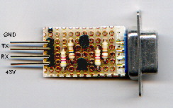
This circuit is just a level translator from RS232 levels (+ and - 12V) to TTL levels ( 0 and 5V). This schematic gets its power from the Nutchip board, through pin 4 of CN2. Transistors are not critical, and any couple of small NPN + PNP transistors will do. This circuit is just cheaper and easier to build from junk parts that equivalent counterparts built from MAX232, etc (more examples on Nutchip's site).
Connect the interface to PC serial port using a standard extension cord, plug
the interface to the board hosting the Nutchip, and switch 5 Volt power on.
|
Programming takes place without leaving Nutstation: make sure you have
selected the correct serial port, then click on "Programma nutchip"
to trigger programming. |
|
|
|