![]()
|
|
|
|
|
|
control anything from a cell phone Tiny Planet: a planet-wide, wireless I/O porta joint project with AVR guru Claudio Lanconelli (http://www.lancos.com) |
|
On December 12, 1901, the scientist and Nobel prize Guglielmo Marconi
was able to transmit across the Atlantic Ocean, for the first time in history.
One century later, wireless communications are ubiquitous and widespread. Everyone
can pick up a cell phone and talk with a friend located in a different continent.
Voice calls are only one of the options: latest cell phones can send faxes,
exchange text messages, e-mails, music, and even connect to the Internet. Said
in other words, whatever the origin of your information, if it can be reduced
to small data packets it can be delivered to a mobile phone.
This circuit connects to the serial port featured by many cellular phones.
Its function is to provide an input and an output port capable of being
remotely controlled using another mobile.
Control takes place by means of SMS (Short text Messages Service). When
the mobile receives a predefined text message, like "Activate burglar alarm"
or "Start backup pump", the circuit automatically recognizes it as a
command, and switches the output accordingly. Besides switching the port
on or off, the user can pulse it for a short period (e.g. "Reboot
remote server").
 Fig. 1
The device can be used as well to notify the status of the input port, sending automatically a message every time the input changes (e.g. "Insufficient level in Tank #5"). To know input status at any time, the device can send back a SMS describing the status of the input, as a response to a request message.
 Fig. 2
SMS are simple and convenient as they can be entered, stored, and read directly
on the cell phone itself. Incoming messages are completed with the time of reception,
and stored automatically in the mobile's memory.
By means of one of the various services offered by network operators they can
be converted to faxes, e-mails, and even voice calls spoken by a synthetic voice.
As an additional benefit, SMS are fairly priced since they don't require precious
real-time bandwidth.
The applications are countless. It can be used to make an extended range
remote control, operable from anywhere in the world. In the industry,
it can monitor if a machine is running, or if some threshold is surpassed. The
technical staffs are alerted automatically and can remotely operate an immediate
countermeasure.
Commercial applications are numerous as well. All the components of a home
automation system can be conveniently controlled and monitored from the
cell phone. To enhance even further its wide applicability, the circuit is very
small and is battery operated.
| As an engineer, that little golden connector on the bottom of my
cell phone always attracted me. After a little Internet browsing, I found the connector pinout of my Ericsson T10s. The signal names confirmed my expectations: audio input and output to connect a external handsfree, mute control, flash programming signal, battery, external power, and at last serial RX and TX. I would have connected it immediately to the PC COM port, but the connector on the mobile is too small to get a reliable contact without risk of damaging the phone. I decided to buy a ready-made data cable; in the meantime, I continued searching for more information about the data protocols. One of the aspects of the Internet that I like most is its capability to seek information straight from the sources. I subscribed to the developer zone on the Ericsson's main site, and after some unsuccessful navigation, I found an interesting message in the forum. This time I was very surprised! |
|
 Photo 1a - The hand-crafted prototype connected to a Ericsson T10S GSM phone |
|
|
|
A little trial and error with the mobile connected to the PC helps understanding the extended-AT command set used by the cell phone. After setting HyperTerminal to 9600,N,8,1 (a lucky guess), I started typing the AT command: AT
And the cell phone answered: |
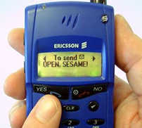 Photo 2 - A great feature of this project is that text messages are customisable |
First, tell the phone which memory to use for successive commands:
AT+CPMS="ME","ME" +CPMS: 7,15,7,15,7,15
OK
This instructs the mobile to use internal memory "ME" in place of the "SM" memory from the SIM (Subscriber Identity Module) as default memory. Next, a message can be read from that memory specifying its number:
AT+CMGR=4
+CMGR: 1,,27 0791934329005000040C9193433728501400001060314104350809D02A735A043DAB54
OK
This is the fourth message, 1= received and read, 27 bytes long text, in PDU
(Protocol Description Unit) format.
The PDU format is quite complex, as it contains many subfields packed
together using different encodings. Among other things, it holds also service
centre numbers, origin numbers, nation codes, a time stamp, and a descriptor
of the character set used.
For more detailed information see the sidebar "SMS
Data Dissected": for our purposes, it is sufficient to know that the text
bytes are on the rightmost position.
Storing a "signature" from the last 6 byte of the message, the device
will be able to recognize incoming messages. Right now, we are able to
download messages from the phone.
The next command frees precious mobile memory deleting the seventh message:
AT+CMGD=7
OK
The last step is to send an SMS message. This proved to be the more
difficult part, as I had to find a workaround in order to avoid building a PDU
from scratch.
The trick is to ask the user to send the message manually, during the
first setup. In this way, the mobile will complete the PDU with all required
fields, it will pack the text and numbers, and it will store it in the sent
messages memory. At a later time, a simple command is all that is required
to resend the message from memory:
AT+CMSS=1
+CMSS :96
OK
Besides being simple for the microcontroller, this technique is simple for
the user too.
I like to call it setup by example: to setup the system which text to
send, which phone numbers to use, and which command to recognise, just send
them once manually (as usual, using the mobile itself), then press the CONFIGURATION
button to make the machine learn them automatically.
Another advantage of using only four among the many "AT" commands available
is an improved compatibility.
Manufacturers introduced minor differences while implementing the standards.
Although it has been tested with the Ericsson T10s, T28 and R320 only,
the circuit should work unmodified with any other mobile supporting the same
command subset. If you try it with different phones please let me know
so that I can update this list.
When I told Claudio about how easy it would be to control things using a mobile
phone, we agreed that the subject was worth a try.
We decided to use the smallest processor and as few external parts as
possible.
The circuit shown in Fig. 1 makes the most of a TINY12L and a transistor, and
is remarkably simple:
Fig. 3- Schematic diagram. The circuit is remarkably
simple, the only active parts are an ATTINY12L and a transistor. Note that capacitor
C3 appears "reversed": it is there to provide negative potentials
required by the RS232 interface.
The TINY12L is an 8-pin microcontroller with 512 words of flash code
memory, 32 registers, and a precious 64 bytes of EEPROM.
Three AA cells, for a total of 4.5 volts, power the circuit.
As the TINY12L has an internal brownout, it can run safely without requiring
a voltage regulator. Apart Vcc and GND, all of the eight pins are available
- including RESET - thank to an internal oscillator running at a respectable
speed of 1 MHz.
With 1 MIPS at our disposal, the serial communications can be handled entirely
in software. Precise timing is not sacrificed by means of an adaptive
algorithm that adapts serial port speed to the internal clock variations
as the battery discharges.
The serial stream enters the chip through PB4. Diode DZ4 and R4 cut the negative
fraction and limit input swing. On the converse, the output stream from PB2
drives the transistor Q1.
On the collector, a negative voltage is derived from the input stream. In this
way, the data output to the cell phone is a true bipolar signal.
The output stream is used as well to drive a LED; it is connected straight
to PB2, and flashes at every transmission.
The pin PB0 is connected to a jumper that tells the software to disable automatic
notification of input changes. It is pulled up internally, the resistor
R6 is used to resolve conflicts during in-system programming. It can
be omitted if the ISP takes place with the jumper removed.
All the pins are assigned to functions that don't impede ISP.
The input goes to pin PB3, which is pulled up internally; the output comes from
pin PB1. Both have a small protection resistor connected in series.
The RESET pin is pulled up with an external resistor, because the internal pull
up is a high value one. By converse, lowering input impedance removes the risk
of picking up noise emanating by the intense electromagnetic field of
the mobile.
The code was written in assembly on the AVR Studio assembler downloadable
for free on the Atmel's web site.
The algorithm at the heart of Tiny Planet is very simple. During setup,
the four messages used as commands and the two messages used as responses are
stored in the phone memory, where they can be read back by the controller
issuing the appropriate extended-AT command.
For every command message, the set-up routine extracts a unique 6-byte "signature"
from the last message bytes, and stores it in EEPROM. The system expects
that every message be stored in a fixed position, as shown in Fig. 4
(to ensure this, delete all of the messages from the mobile prior to set
up).

Fig. 4 - To compare variable length messages without RAM, messages are reduced
to signatures.
To check if a new SMS is valid, its signature is compared against the authorized
set.
The 6-byte signatures for each of the 4 commands are stored in EEPROM
Outgoing messages are in positions #1 and #2, for indicating a low input and a high input respectively. Ingoing command messages are in position #3 (request to report the input status), #4 (command to pulse output), #5 (command to set output) and #6 (command to clear output). Position #7 is kept free for incoming command messages.
During operation, the device repeatedly checks the message memory
#7 for the presence of a new SMS.
When it finds a new message, it compares its signature against all the stored
versions. If one of the signatures matches, the relevant command (pulse
output, set output, clear output, or send-back input status) is executed.
Using signatures instead of the full text allows the system to save eeprom,
and makes arbitrary-length messages possible. The system is safe as well,
requiring an exact match of the last 6 characters to accept a command.
The "send input status" command, as well as a level change of the
input pin when the AUTOSEND jumper is open, causes
a message to be sent out.
It is neither necessary to recreate the outgoing message by scratch, nor to
store it in EEPROM, as it is sufficient to re-send the first or the second message
from the mobile message storage, according to the status of the input
pin.
At the end of the cycle, the message #7 is cleared from memory and the system
is ready for a new command.
| The software implements low-power techniques, which extend battery
life to more than a year of continued use using AA cells. The TINY12 is perfectly suited to run on batteries. Most of the time the controller is in sleep mode, with only the watchdog on. In this condition, power consumption is only 200 µA. Control is resumed when the watchdog expires (a couple of seconds), or when the input pin changes, thanks to the "wakeup on pin change" capability of the TINY12. When running the required current is about 1 mA, for a period as short as 20 mS. Every 10 short breaks (about 20 sec) the micro controller starts a longer dialogue with the mobile, requiring an extra 840 mS at 1,2 mA (on the left in Fig. 5). As the circuit run on the internal oscillator, the clock frequency varies over battery lifetime. The serial port routines implement an auto-baud algorithm that adapts its timing as clock changes. To save another nibble of energy, the calibration value is stored in eeprom and the calibration is repeated only when needed. Last but not least, the circuit must behave correctly when still connected to a discharged battery. The prototype passed the test brilliantly: the internal brownout halted the controller as expected. |
 Fig. 5 - Current drawn. The prototype can run on three AA cells for more than a year. |
| As the circuit is made of a small number of parts, we skipped the preparation
of a PCB replacing it with a breadboard. All the components are through-hole, except the TINY12 that is a surface mount device. But who's afraid of SMD? Just solder a row of 50-mils pin-strip to each side of the IC. In order to fit the 100 mils spaced breadboard, gently bend the legs of the "spider" (See Photo 3). Fortunately the TINY can be programmed in-system, so it doesn't need to be removed! Fitting the remaining parts was a breeze; the finished board looks spacious and clean. The circuit and the batteries are enclosed in a small plastic box. From one end of the box, we cut the holes for the CONFIGURATION button, the LED and the connector for the input and the output (actually a four poles RJ45). You may wish to replace the AUTOSEND jumper with a panel switch and place it on the front panel. I found this unnecessary. On the opposite end, we cut the hole for the D-type connector for the serial port. When all the components are in place and the board is double checked for errors, the programming can take place. We used the excellent PonyProg software written by Claudio, powering the board with 5 volts from a bench supply. The finished prototype is very compact and professional looking. The box is about the same size of the cell phone. Packed together, they can be placed practically everywhere. |
 Photo 3 -This is how I solder a 50 mils part on a 100 mils breadboard. Programming is done in-system via the strip socket (on top). |
| The device is very simple to use. The text messages
for both commands and readouts are fully customisable by the user.
Plain text messages like "Activate burglar alarm" or "Main engine is running" are OK. Just ensure that the at least one out of the last 6 characters is different for every command. To prepare your system for set up, first switch on the mobile, then connect it to Tiny Planet using a suitable data cable. This is the "slave" phone, to differentiate it from the "master" phone, used to issue commands. To set up a new set of messages, just send them in the usual way, using the cell phones themselves for editing, according to the sequence below. |
TIP: With
my cable (a ready made made-in-ROC clone) the phone behaves differently
if the cable is connected to the phone before or after it
is powered on.
In one case it starts automatically in "diagnostic mode " at 115200 baud. On the opposite case it is ready to accept 9600 baud AT commands. |
First, begin from the slave mobile:
The messages above must be sent anyway, even if you are not going to
use the input port feature of Tiny Planet.
Next, it is time to move to the master mobile, that is the phone you
use to issue commands:
Again, all of the messages must be sent even if you are not planning to use
a specified command. When all the seven messages are received, press the CONFIGURATION
button on Tiny Planet.
The LED flashes until setup is complete. That's it!
If your application doesn't require automatic notification of the input changes,
remember to close the AUTOSEND jumper.
When the system is running, the LED flashes once every 20-25 seconds.
I like clean designs with great potential because of (and not despite of) their
simplicity.
Tiny planet is a simple, flexible and portable solution, useful for a wide range
of applications.
It is a very optimised design, that doesn't even use a voltage regulator,
and makes profitable use of every feature of its components: EEPROM,
brownout, internal oscillator, watchdog, wakeup on pin change, in-system programming,
sleep modes.
The code is dense, including power management and adaptive baud generator
in just 417 out of 512 words available. Still, there is enough space for adding
new features or to modify the behaviour to suit your personal taste.
For example, you may want to notify the same alarm to three different phone
numbers instead of one.
Making designs as simple as possible (but not simpler!) improves every
aspect of a product.
The result costs less, is easier to manufacture, has a smaller size (even in
its actual hand crafted form!) and costs less to package and ship. A lean BOM
(bill of materials) is also the best insurance from parts shortages.
All these aspects contribute to increasing both profitability and added value.
The user interface we developed is remarkable as well. Most of the work
is carried on the cell phone, in a way the user already knows, so that
a pushbutton and a single-page user manual is all that it is needed.
Compare this to a PC running internationalised software, as required to set
up most industrial GSM modems!
But the characteristic that I like most is that this little, cheap circuit
allows everyone to start experiment with a mobile phone, discovering a dynamic
world that opens new, exciting and unparalleled possibilities.
A world discovered 100 years ago by Marconi's invention, that ever since has
made our planet very, very, tiny.
|
|
ARTICLE CODE (.zip, 11 kB) includes assembly source code and binary files (AVR Studio 3 project ) | |
 |
BUY TINY PLANET already built, encased, with cable for Ericcson T28 and R320 (not the T10s described in the article) |
|
Claudio Lanconelli is the author of PonyProg, a powerful programmer for several microcontrollers and serial eeproms. He has several years of experience designing hardware and software for embedded systems. Some of his interests include home automation, Linux and networking. You may reach him at lancos @ libero.it or visit his web site at www.lancos.com
|
Alberto Ricci Bitti holds a degree in Computer Science from the University of Milan. He has 10 years working experience designing and writing software for embedded systems. In its free time he enjoys competing in design contests, were he awarded several prizes. Currently he is a designer for Eptar, an industrial controllers and instrumentation firm. You can visit his web page at www.riccibitti.com or contact him at a.riccibitti @ iname.com
|
|
|
REFERENCES [1] ETSI GSM 03.40: [2] ETSI GSM 04.11: Digital cellular telecommunication system (Phase 2+), Point-to-Point (PP) Short Message Service (SMS) support on mobile radio interface [3] Ericsson T28 AT command online reference http://mobileinternet.ericsson.se/ |
RESOURCES European Telecommunications Standards Institute (ETSI):
Ericsson developer zone: PonyProg Free Programming Software
AT-TINY-12
|

|
|
|