|
|
|
|
|
interfaces to gate openers
rings the bell when someone's crossing the gate
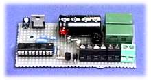
Dear old bell... | Schematic diagram | Truth table | Prototype
|
Long time ago, it was usual for shop doors to have a tiny bell. Opening
the door would cause the bell to ring, telling the shop personnel a new
customer arrived.
|
the prototype has been assembled on a experiment printed circuit board |
The circuit is easy to master once we divide it in its four main bloks:
| POWER SUPPLY: it takes advantage of the 24V (dc or ac) normally present in automatic openers |
INPUT: "detects" the status of the existing photocell, without interfering with its normal function |
LOGIC: The Nutchip contains all control logic |
OUTPUT: rings the existing door bell |
M1 is a clamp connected to the 24V (dc or ac) power from the gate opener. The diode bridge rectifies the alternate voltage (should the opener use dc current, it merely adjust the positive and negative rail to match circuit polarity), in order to get the power required by the 24 V relay. The same potential, limited in current by the series resistor R1, feeds the 5V regulator IC1. The 5V stabilized voltage from IC1 powers the Nutchip; the R3-C5 network ensures proper RESET to the chip.
The input stage consists of a double switch relay, RELAY1. The original photocell's output connects to M2, therefore it powers the relay. RELAY1 clones the situation it sees on M2: it is energized when the photocell contact is closed, and it is released when the photocell contact is open. As a consequence, relay switches follow the original photocell behaviour. One of the two switches available in RELAY1 is brought to M3, in order to act as a replacement of the original photocell which is now connected to M2. The other is used internally by the circuit in order to detect the photocell signal. This second switch connects to Nutchip input IN1, letting him to know when someone enters the photocell range.
|
|
The output stage consists of the relay RELAY2 and its driver transistor Q1. We adopted a 24V dc relay in order not to overload the 5V regulator IC. Limiting the load to the Nutchip alone limits the power required from IC1, making an heatsink unnecessary. It is important to limit heat as much as possible in circuits intended for continuous operation, as the less heat produced, the longer the circuit's life. The clamp M4 connects in parallel with the existing doorbell pushbutton (the doorbell rings when RELAY2 is energized). Al the relay is in parallel, the doorbell will also continue to work as an ordinary doorbell.
The circuit logic is managed entirely by the Nutchip, as described in the following.
|
R1 390 ohm resistor 1/2W |
D1 diode 1N4007 |
The inner logic is very straightforward. When the circuit is powered up for the first time, the doorbeel rings continuosly for a couple of seconds. This comes handy should you need to test if the circuit is working (the doorbell relay must energize as soon as the circuit is powered) and if the doorbell is connected correctly.
Once the 2 seconds period has elapsed, the circuit passes to state st01, where it wait indefinitely until the input IN1 goes to logic 0 (which means the photocell is activated). Here there is a little trick. As all circuits operating in harsh environments, because of the noise produced by contactors and nearby electric motors, it is possibile for the circuit to detect a noise spike. In the state st02 we wait as little as 10 mS (0.01 seconds), prior to to make a second check on the input IN1 (state st03). If it is still low, the we can reasonably assume that it was a real photocell signal; otherwise, it was a momentary condition due to external interference and we ignore it, getting back to state st01.
When a photocell signal is detected, we want to emit a special ring pattern.
We selected a longer tone, followed by three short pulses (beeeeeeeep beep bepp
beep). This pattern is very well distingushable, but you can change to a different
one if you don't like it. We build that cadence with a series of timeouts, passing
from state st04 up to st10.
 Nutchip state table file "annunciator.nut" |
COMMENTS
TRANSLATED
|
In case of many people crossing the gate, as in the case of a factory entrance during rush hours, a bell ringing continuously can be annoying. Another case is when someone stops right on the door threshold! In order to make circuit operation useful and enjoyable, the Nutchip acts with two countermeasures. State st11 wait for the photocell to be free from obstacles before continuing. Therefore, should someone stop in front of it, the bell rings only once. Moreover, state st12 iintroduces a 30 seconds "blind time" during which the circuit purposedly ignores any input. This time proven to be fine with our tests, but you can set it to any other period you think appropriate.
This circuit should be easy to build on a piece of perf board (see photo). Usually, this circuit will be placed inside a small plastic or metal box: it's a good idea to get one before starting to assemble the prototype, just to be sure that everything fits nicely. Also, don't forget to keep some board space for fastening the board to the box.
As this circuit does not provide a programming connector, you need to program the Nutchip prior to place it on the board (a socket is recommended, tough). Always fit the Nutchip in place as the last component, after checking that all the other parts are correctly connected and working. In particular, check for the power regulator to supply the required 5V potential before fitting the Nutchip (of course, remove power while fitting it in!).