![]()
|
|
|
|
|
A simple LED flasher
|
Get to know Mr. Nutchip with a simple LED flasher.
An easy and fun experience to get in touch with all the details of design and
experimenting with Nutchips.
OUT1, OUT2, OUT3 and OUT4 are the four Nutchip outputs. Each output
can be either at logic level zero or one.
Putting an output to zero (aka low level) means that its respective pin
measures about zero volt. In this condition a Nutchip output can sink
up to 10 mA.
Opposite to low level, an output at logic level one (aka high level)
presents on the pin a voltage close to the power supply, about 5 volt
for Nutchips. An output can source up to 10 mA.
With Nutchips, the output states are not fixed by the manufacturer: you decide wich combination of zero and ones are appropriate for the outputs. You write a truth table in which every outputs combination is bound to a specific combination of the inputs and internal state. The more states you add to the table, the more different combinations you can get for the outputs. We will get back on this topic later.
|
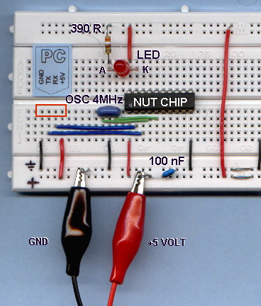
To make a LED flasher a single output will suffice. A three pin ceramic resonator provides the clock pace for the system
to work. To complete the circuit, a 100 nF capacitor is required by the
chip for smoothing noise on the power supply. |
WHY THE LED IS ON WHEN
THE OUTPUT IS OFF? A LED is a diode that emits light when it is traversed by a current ranging from 1 to 20 mA. A way to make a current flow through a device is to connect it between a positive and a negative poles. Here the positive pole is the positive supply rail, namely +5V, while the negative pole is connected to the ground, represented by a sort of arrow (see pin 10). An output at logic level one measures +5V, the same as the positive pole. Connecting an LED between the positive and an output at the same voltage as the positive pole does not provide any current flow for the LED. The LED is OFF. What if the output goes to logic level zero? Logic zero is zero volt, the same as the negative pole. Connecting an LED between the positive pole and an output at the same voltage as the negative pole provides the current flow to turn the LED ON. Magic, isn't it? As for the LED polarity, always remember that the arrow in its symbol must point in the direction of the current flow, that is from positive to negative. |
|
PARTS LIST
|
|
|
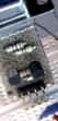
The circuit is very simple, and can be built on a solderless breadboard. Be careful not to reverse the Nutchip, its pin 1 must be correctly aligned: the picture shows it in the lower left corner relative to IC body, near to the ceramic resonator (OSC). Nutchip pin 1 is also marked by a small slot or a dot on the IC case, and looking it afrom above,the other pins have increasing numbers running counterclockwise. LEDs have a polarity too: the catode (K) is the pin with the bar in the
schematic. This pin is usually shorter, and the case has a flat face near
it. The anode (A) is the pin with the arrow symbol in the schematic. Refer to the photo for completing the circuit with all the connections;
try to conform to the standard colors of red wire for the positive pole,
and black for negative. |
 |
The hardware part is finished, but the board cannot work yet. In fact, the
Nutchip we have put in the breadboard does not know how to move its output
pins and what the inputs mean! We are going to write a truth table and
to download it to the chip.
A truth table lists all of the valid input configurations and chip internal
states, ruling the values shown by the outputs, and how internal states should
succeed.
We can start from a blank truth table, then add the device internal states
one after another. For each state, we add a series of input conditions:
when an input condition is satisfied, the Nutchip changes its internal
state. The new state is written in the table as well.
For each state, the table determines the output values (which output is zero
and which is one). Changing the state is the Nutchip unique way to change the
outputs.
Let's make a practical example with our flasher. What are a flasher states? Well, a simple flasher counts just two states:
Let's use pencil and paper to write schematically such a table. Likely you will end up with with a table like this one:
|
STATE NUMBER |
OUTPUT |
CONDITION AND NEXT STATE |
|
ST. 0 |
PUT LED OFF |
AFTER 0.5 SECONDS CHANGE STATE TO ST. 1 |
|
ST. 1 |
PUT LED ON |
AFTER 0.5 SECONDS CHANGE STATE TO ST. 0 |
The first column is the state number. States are identified with increasing
numbers, usually starting from zero. The state zero is also the state
the Nutchip will enter at power on, and when it is forced to RESET with
a special pin.
The following column determines the outputs for a each state: you see
from the circuit diagram that our LED is connected to an output (OUT4). Filling
this table cell you decide if the LED will be ON (OUT4=0, as explained previously)
or OFF (OUT4=1)
The rightmost column lists the conditions for changing the internal
state. Should a condition become true, the chip will change its
state assuming the state specified by the condition itself.
Here the two states have a very similar condition. The condition is that
some amount of time has elapsed: which is initially false (state does not change),
and becomes true after half a second (state changes).
FOR SIMPLICITY'S SAKE, WE LIMITED THIS EXAMPLE TO TIMEOUTS...
...this is quite limitative, restricting application areas to simple sequencers. Nutchips allow you to build condition much more complex than this, allowing multiple conditions for each state, including checking for any combination of the values at the inputs, and even for the keypresses from the built-in remote control decoder.
Turning our paper-and-pencil truth table to a professional looking one, suitable
for Nutchip downloading, is a smooth process.
You need a PC running Nutstation (more info about Nutstation setup
and usage).
When finished, the table will look like this:
Nutstation's snapshot of the finished table of the flasher.
It's easy to spot a close resemblance with out prevoius paper-and pencil truth table:
| STEP BY STEP PROCEDURE for
creating the LED flasher truth table Click on
Note: the table is istored in the file "led_flasher.nut" supplied with Nutstation. |
Click on the "Prog. chip" tab to display this page:
The light gray area on the left is an automatically generated report. The percentage shown refers to the fraction of Nutchip memory used by the current truth table. If you don't see it, there is some kind of error on the truth table that needs to be fixed before downloading it to the chip.
If your table is incorrect, the programming button is disabled. Nutstation checks automatically the truth table as you enter it. Errors are spotted in real time and invalid cells are highlighted in red.
This is the best time to check for correct serial port selection. You need
to configure it only once: click on ![]() to bring up the serial port selection
window.
to bring up the serial port selection
window.
 |
Assuming that everything is OK, fit the programming interface to the breadboard (picture on the left) as switch the 5 volt dc power on (be careful not to reverse the polarity!) Cross your fingers and click on the programming button (shown
on the right) Congratulations, your LED flasher is complete! |
With both timeouts set to 500mS, the LED flashes exactly once per second. Try to change the times: for example, LED switched on for 1 second as off for 5 seconds. Try also LED on for 0.1 seconds (100 mS) and off for 0.9 seconds (900 mS).
Try these times too: LED on for 5 mS and off for 20 mS: what happens? The LED appears continuously lit, even if its light is slightly dimmed... Try to look at the LED from the opposite corner of your room while shaking your heard quickly: the light breaks in segments!!!
Circuits as simple as this one are best suited as building block for more complex devices. A simple timer can be built connecting a relay (using an appropriate driver) in place of the LED. Replacing the LED with a buzzer makes a simple pulsed audible alarm. Take a look to the "schemi base" page from the original site to get some hints and tips.
You can read both these from www.nutchip.com
: I hope this short introduction gives you the right background in order continue
with automatic translation tools like those provided on-line by Altavista
or Google.
In order to give you an idea of what can be done with a Nutchip, with a very
simple truth table and few external components, the next translated project
is a fantastic wireless alarm system complete with
building plans.
|
|
|