
|
The Life Energy | The Rotorgon | The Orgonometer | The Magnetorgon | Tables and Figures | The author | PDF version | Old Site (only italian) | Main Page |
THE ROTORGON
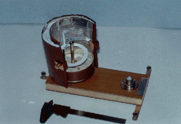
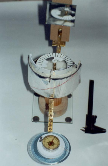
 The pin pivot can be
obtained from one end of a needle. The collector consists of a
cardboard disk (having diameter of 16-18 mm) with a hole in the center,
in which the pivot, by a drop of glue, is fixed. The halo has
three or four arms, fold downward with the function to lower the centre
of gravity of the entire moving structure against the support point of
the pivot. The arms can be obtained from a copper or steel wire (0.3 mm
thick), opportunely shaped and welded to the collector disk through a
little of glue. Instead of metal wires, paper streams can be used for,
as well. The advantage in using paper streams is to notably reduce the
weight of the moving structure (table 2A). Finally, the ring is
obtained by designing and cutting out from a paper sheet (that used for
printer is good enough) a double ring having external diameter of about
80-90 mm and internal diameter of 60-70 mm. Then, the ring will be
connected to the arms of the halo by a drop of glue. It is mandatory
now to clarify what position the rotor has, once it has been mounted on
the conical bearing (blind hole), in respect to the semi box. It is,
for an half part, protected by the half box, and the remaining
half part, is exposed to the surrounding environment. This condition
must be carefully followed and satisfied in order to make the
instrument functioning. Other solutions, with some changes carried out
on the above mentioned one, have been useful tested, as well. For
instance, we obtained good results when the cut part of the box is just
a little less than a half, in such a way to reduce the free space with
the advantage to have more available space for the orgone accumulator.
In this way, we do not have anymore a plane of diametrical section, but
two planes angled between them 120° (instead of 180°). The wall
of the half box, wrapping the half rotor, is cased with iron sheet, at
distance of about 1-2 cm from the edge of the rotor. It is advisable
not to reduce this distance if you want to avoid the rotor blocking up
by the attraction exerted by the wall.
The pin pivot can be
obtained from one end of a needle. The collector consists of a
cardboard disk (having diameter of 16-18 mm) with a hole in the center,
in which the pivot, by a drop of glue, is fixed. The halo has
three or four arms, fold downward with the function to lower the centre
of gravity of the entire moving structure against the support point of
the pivot. The arms can be obtained from a copper or steel wire (0.3 mm
thick), opportunely shaped and welded to the collector disk through a
little of glue. Instead of metal wires, paper streams can be used for,
as well. The advantage in using paper streams is to notably reduce the
weight of the moving structure (table 2A). Finally, the ring is
obtained by designing and cutting out from a paper sheet (that used for
printer is good enough) a double ring having external diameter of about
80-90 mm and internal diameter of 60-70 mm. Then, the ring will be
connected to the arms of the halo by a drop of glue. It is mandatory
now to clarify what position the rotor has, once it has been mounted on
the conical bearing (blind hole), in respect to the semi box. It is,
for an half part, protected by the half box, and the remaining
half part, is exposed to the surrounding environment. This condition
must be carefully followed and satisfied in order to make the
instrument functioning. Other solutions, with some changes carried out
on the above mentioned one, have been useful tested, as well. For
instance, we obtained good results when the cut part of the box is just
a little less than a half, in such a way to reduce the free space with
the advantage to have more available space for the orgone accumulator.
In this way, we do not have anymore a plane of diametrical section, but
two planes angled between them 120° (instead of 180°). The wall
of the half box, wrapping the half rotor, is cased with iron sheet, at
distance of about 1-2 cm from the edge of the rotor. It is advisable
not to reduce this distance if you want to avoid the rotor blocking up
by the attraction exerted by the wall.
How to use it
If we charge the instrument by laying on the hands,
even though at few millimetres far from the wall of the box and/or the
bottom, we can observe that the rotor soon starts rotating. The
rotation velocity depends on the duration of the charge and from the
intensity of the transmitted energy. With good working condition, 18-20
rpm can be reached. The direction of the rotation depends on the
instrument orientation versus the cardinal points. We have observed
that if the direction E-W passes through the middle line of the box (or
symmetry axis of the box, from the perpendicular plane to that one the
box has been sectioned), in such a way the concave part of the box is
oriented to W, the direction of the rotor rotation is almost always
counterclockwise. Only in presence of atmospheric disturbance the
direction of the rotation tends to reverse, as we discuss in the next
chapter. In the case the orientation of the instrument is reversed,
with the concave part of the half box towards E, the direction of the
rotor rotation also changes and promptly reverts becoming clockwise.
This could induce to think on the existence of an energetic current
that passes through the instrument from W to E, according to the theory
of the propagation of the cosmic orgonic wave. Charges induced by
laying on the hands would not have other function that powering the
weak energy channelled by the orgonic wave. According to this theory,
the instrument would be affected from the combined influence of a main
wave amplified and modulated by a local source of life energy.
From this point of view the Rotorgon not always is able to make a
reliable measurement of the intensity of the energy radiating from the
hands, not being able to identify this energy from that one related to
the orgonic wave that flows through. This would be confirmed by the
fact that, keeping constant any other variable, laying the hands alone
on the instrument, in order to induce in the rotor a constant rotation
velocity, is not enough. On the contrary, we have seen that this
velocity changes, keeping constant the psycho-physical condition of the
operator, when other variables such as the atmospheric conditions
change. Someone sees the spontaneous rotational motion of the rotor in
somehow correlated to the dynamic nature of the orgonic energy that
should have the characteristic to propagate itself by waves and in a
spiral-shaped form. In particular condition a vortex could form
inducing the rotation of the paper ring (rotor) immersed in this
rotational field, as for a sort of electrostatic induction. It is a
matter of fact that supplying electrostatic charges to the external
coating of the stator power the performances of the Rotorgon, and this
is well evident by a sudden acceleration of the rotor. The charge of
the instrument can be also done by means of a glow-lamp (60-80 W), put
at distance of 50-60 cm. In the case the instrument is subjected to an
intermittent light lamp, the stopped rotor, starts rotating and
accelerating as the frequency of the lamp gradually increases. However,
it is very difficult to establish a synchronism between the light
frequency and the rotation velocity of the rotor, that firstly
accelerates and then goes out of phase, slows down and sometime stops.
In this case variables not yet well known, such as the orgone
accumulator, that can hold back part of the energy coming from the
outside, and release the remaining one and perhaps also transform it,
can play an important role. Generally, before to definitively stop, the
rotor presents an intermittent motion: it stops, stays stopped for few
seconds (the time needed for recharging) and then restarts rotating for
some minutes and then it stops again. Definitive stopping is preceded
by longer and longer stops. In this case it has been seen that usually
the instrument continues working even with bad atmospheric condition
(overcast or rain). In the case the bad weather lasts for some days,
the rotor stops just after the charging. In fact, the Rotorgon works,
once charged, by means of the flow of the orgonic wave passing through.
This wave is thought having a pulsating nature and channels an energy
depending on several parameters such as the weather condition. One of
the variables that can affect the stopping of the rotor is the presence
of the operator, mostly when he is entering the room where the
instrument is located. It is well known from the syntropic principle
(negative entropy), valid for all the living system, that a system with
higher orgonotic potential draws energy to one at lower energetic
level. In this case a flow of energy from the instrument to the
operator is to be expected. When the instrument is completely charged,
it has been seen that the opposite can happens. It is suggested to
prepare the experiments in such a way to have a remote control of the
instrument functioning, in order to avoid compromising the results of
the test. A similar phenomenon to that above described can be observed
even when approaching a plant or flowers to the running Rotorgon: the
rotor definitively stops.
Duration of the charge
The duration of the charge is function of the
orgonic potential of the environment: the lower is the difference of
potential between the instrument and the environment, the longer is the
duration of the discharge. However, when this time is higher than 24
hours, it seems we can not speak anymore about a discharge of the
instrument. In this case, we can think about a sort of supply of local
orgonic current to the instrument. This point is extremely interesting
and would deserve to be studied in deep through systematic experiments.
When we observe a so long and autonomous rotation of the rotor, with
continuos and regular night and day motion, we are nearly forced to
think about a supply of orgone energy from the surrounding environment.
Lately, we observed that the spontaneous motion of the rotor is
practically perpetual, night and day, even if interrupted, every so
often, for short breaks needed for recharging.
The critical potential
The critical potential of the Rotorgon (Pcr) is the
lowest level of energy needed to overcome the inertial forces of the
moving structure and the modest friction of the pivot pin on its
bearing. This value is a constructive characteristic of the instrument
and represents the threshold above which the Rotorgon starts rotating.
When the instrument is located in an environment having an energetic
potential not high enough to continuously maintain in rotation the
rotor (environment poor in life charge) but with an energetic level
value almost equal to the critical potential Pcr, even a very low
orgonic current can be detected by the instrument. In fact, the energy
coming from this orgonic current, even having a potential lower than
Pcr, is stored in the stator that, as we have said, is provided with an
orgone accumulator. After sometime, the storing of this energy
determines the increase of the stator potential (in the same way the
storing of heat determines an increase in temperature) until to
overcome the Pcr value. So, the rotor starts and keeps on rotating for
a period depending on the quantity of the stored energy. During this
phase, that we can call active phase, the instrument
discharges, under the form of kinetic energy, the potential energy
stored in the previous charging phase (called passive phase).
In the case, the instrument is located in an environment where the
potential is much lower than Pcr (unhealthy air and/or with high
humidity and pollution agents), we have to supply energy (through a
lamp, putting the instrument in a sunny location, radiating energy by
laying on the hands, etc) to the instrument if we want it to detect the
presence of the orgone current of the environment. On the contrary, we
have to wait that the weather and seasonal conditions change, with the
presence of a sufficiently active orgone energy flow, that promotes the
rotation of the rotor. Lastly, if the atmospheric and environmental
conditions are good enough, with a local orgone potential higher than
Pcr, the instrument will have performances absolutely unexpected. Then,
the rotor will detect, with its spontaneous, active and constant
motion, all the power coming from the orgone wave. In this case, we can
see, at any hour of the night and the day, that the rotation of the
paper ring is very akin to something of living-like.
The orgonic wave
The orgonic wave that passes through the instrument
consists of two semi-waves: the former is positive (peak) and the
latter is negative (valley). The peak, with a potential higher than
Pcr, induces the rotation of the rotor, while the negative semi-wave,
with potential lower than Pcr, is not able to maintain it in rotation.
The presence of an orgone wave is put in evidence by the Rotorgon even
when, in favourable condition, the instrument continuously works. In
fact, the motion of the rotor is almost never an uniform rotational
motion, namely at constant velocity, but varies since the rotor is
subjected to continue acceleration and deceleration. This can induce to
think about a presence of an energy flow variable over the time. The
instrument, immersed in an energy field that passes through, can
works by itself, without supplying energy, provided that the
environment can help it to. It is something like what happens to a
galena radio. In this case, the channelled energy of the
electromagnetic wave is able to make the membrane of the cuff hearing
vibrating. The modulated wave is rectified from the crystal and made
audible, but it is not amplified. If we want to pick up a remote
station, and detect waves that channel lower energy, we have to recur
to a local source of energy, amplifying the coming wave that then goes
to feed the loudspeaker. In the same way the Rotorgon does and works.
When the orgonic wave is particularly intense and/or the environmental
conditions permit, the instrument detects it without the help of
additional energy. When the wave is feeble and the instrument works in
unfavourable conditions, it is necessary to feed it by
supplying an additional energy, that primes the functioning. The
function of the lamp (or any other auxiliary mean) can be compared to
that of the current that feeds a radio device.
In case this could be an electromagnetic wave (but it
is not), it should belong to the field of the long waves. The obtained
value for l has
been confirmed, as we can see later on, by measurements performed by
using the Orgonometer. From the period T we can calculate the
frequency, as follows: F = 1/T = 0,04 cycle/sec = 2,4 cycle/min
This velocity of the rotor belongs to the velocity range between 2 and
3 rpm. Based on this value, we can think that the velocities recorded
by the Rotorgon, are nothing else that frequencies of as many different
orgonic waves and that, what we have defined up to now as orgonic
wave, in reality is the result of a bundle of (etheric) waves.
Therefore the range of the waves detected by the instrument should be
between 1000 and 10000 m.
The Rotorgon and meteorology
 The variation of the weather conditions affects the performances of the
instrument. This fact should not astonish if we think that every
atmospheric disturbance always comes with more or less big variations
of the physical parameters of the atmosphere (such as pressure,
temperature, and air humidity), and particularly by a sudden change of
the electric potential, and type and grade of ionisation. For instance,
we observed that a good weather condition (shining sun in a clear sky)
corresponds to the rotation of the rotor always in the same way.
Obviously, the direction of rotation is function of the orientation of
the instrument. So, when the instrument is oriented to W and we are
seated in front of it, with the forehead to N, the direction of
rotation always will be counterclockwise. The rotor tends assuming the
characteristic undulatory behaviour of the velocity: it rotates with
velocity that regularly increases and decreases, and never stops. When
a weather disturbance comes from W, we know that the direction of the
orgonic current inverts and, rather than propagates from W to E, will
be directed from E to W. We can detect this change at first with an
uncertainty in the direction of rotor rotation, becoming alternate, and
then with a permanent inversion of the rotation direction. In presence
of strong gusts of wind, that usually precede the thunderstorm caused
by an advancing cold front, the released energy due to the merging of
air masses at different electrical potential is such that the rotation
of the rotor is nimble and active, as never before. It starts rotating
by itself, without the help of external means, with constant velocity
and continuously, clockwise, when the instrument is North or West
oriented. In the case we are between two disturbances, even some
hundreds of kilometres far, the former from E and the latter from W,
the rotor detects this condition with a nearly absolute immobility. It
is not at all able to respond to any external stress if not after some
time and ends to assume a stall position. An analogous phenomenon can
be observed when the area in which we perform the experiments is
interested by a low pressure that extends also to a huge surrounding
area: the rotation becomes very slow (1-2 rpm), even under the action
of a lamp and the direction of rotation is sometime to the right and
sometime to the left (alternate), with both orientations (to N or W).
It seems attending to a stop of the propagation of the wave, whose
effect would be that to create a pulsating field. We have seen that the
mean velocity of rotor rotation is a recurring factor and one of the
most significant because it gives us an useful indication about the
intensity of the wave detected by the instrument, even though a more
accurate evaluation of such a intensity is possible to obtain only by
using an instrument called Orgonometer. The velocity of the
rotor can be classified as follows:
The variation of the weather conditions affects the performances of the
instrument. This fact should not astonish if we think that every
atmospheric disturbance always comes with more or less big variations
of the physical parameters of the atmosphere (such as pressure,
temperature, and air humidity), and particularly by a sudden change of
the electric potential, and type and grade of ionisation. For instance,
we observed that a good weather condition (shining sun in a clear sky)
corresponds to the rotation of the rotor always in the same way.
Obviously, the direction of rotation is function of the orientation of
the instrument. So, when the instrument is oriented to W and we are
seated in front of it, with the forehead to N, the direction of
rotation always will be counterclockwise. The rotor tends assuming the
characteristic undulatory behaviour of the velocity: it rotates with
velocity that regularly increases and decreases, and never stops. When
a weather disturbance comes from W, we know that the direction of the
orgonic current inverts and, rather than propagates from W to E, will
be directed from E to W. We can detect this change at first with an
uncertainty in the direction of rotor rotation, becoming alternate, and
then with a permanent inversion of the rotation direction. In presence
of strong gusts of wind, that usually precede the thunderstorm caused
by an advancing cold front, the released energy due to the merging of
air masses at different electrical potential is such that the rotation
of the rotor is nimble and active, as never before. It starts rotating
by itself, without the help of external means, with constant velocity
and continuously, clockwise, when the instrument is North or West
oriented. In the case we are between two disturbances, even some
hundreds of kilometres far, the former from E and the latter from W,
the rotor detects this condition with a nearly absolute immobility. It
is not at all able to respond to any external stress if not after some
time and ends to assume a stall position. An analogous phenomenon can
be observed when the area in which we perform the experiments is
interested by a low pressure that extends also to a huge surrounding
area: the rotation becomes very slow (1-2 rpm), even under the action
of a lamp and the direction of rotation is sometime to the right and
sometime to the left (alternate), with both orientations (to N or W).
It seems attending to a stop of the propagation of the wave, whose
effect would be that to create a pulsating field. We have seen that the
mean velocity of rotor rotation is a recurring factor and one of the
most significant because it gives us an useful indication about the
intensity of the wave detected by the instrument, even though a more
accurate evaluation of such a intensity is possible to obtain only by
using an instrument called Orgonometer. The velocity of the
rotor can be classified as follows:
Besides, from some observations, we have also seen that the rotor rotation can be affected by astronomical events such as lunar phases, solstices, equinoxes, sunspots, eclipses, etc.
Hypothesis on the basic principle on the rotor rotation
Electrical test performed on the
Rotorgon outlined a polarisation of the orgone accumulator (the same
phenomenon was also observed on the Magnetorgon). We found out the two
jambs (or the extreme vertical borders of the box internal side) of the
semi-box have opposite electric charge. The potential difference
measured between the stator jambs, when opportunely screened, is of the
order of some tenths of milliVolts (0.1-0.8 mV) as we can see better
later on (see figures 4, 6 and 7).
We can suppose the left border of the half box (seeing while facing it)
has positive sign and the right one has negative sign. As known, the
paper ring is half-immersed in air in which always you can find
positive and negative ions. So, depending on the prevailing of one the
signs of the air ionic charge, the paper ring could be charged with
positive or negative ions. In the first case the ring will be rejected
from the positive charge present on the left jamb and attracted by the
negative-charged right jamb.
In this way the ring will have a counterclockwise rotation motion (see picture 1 in fig. 1A). When, in
the environment, in which the Rotorgon is located, prevails negative
ions, the paper ring, when the air is particularly dry, is charged with
negative sign, and it is rejected by the same sign of the right jamb
and attracted by the positive sign of the left jamb, starting a
right-handed or clockwise rotation motion (see picture 2 in fig. 1A).
Inside the semi-box the ring should result free from charges since the
charges, whose it was the carrier, were neutralised by those of the
respective jambs. The above hypothesis on the rotor rotation basic
principle grounds on the following experimental observations:
1. when the rotor is completely located inside a closed orgone
accumulator, such as the traditional ones, and hence, isolated from the
outside environment, it does not rotate at all;
2. when the orientation of the Rotorgon is inverted, i. e. from
West-East to East-West, it can be seen that also the direction of the
rotor rotation is inverted, having constant the sign of the ionic
charges of the air. In fact, the polarisation of the jambs is function
of its position;
3. It is possible to change the orientation West-East to East-West,
just rotating the stator on its pivot. In doing that the position of
the jambs is inverted: A moves to the B position, and vice versa, but
the sign remains in the same position: now you can find B positive and
A negative (see picture 3 in fig. 1A).
Seeing the semi-box facing it, the left jambs (A), that before was
positive, now is become negative and also the rotor motion is inverted
from counterclockwise to clockwise.
We can deduce that the sign of the jambs depends on the their
position or its orientation in the space, and namely from the
angulation the orgonic current has when flowing towards the
accumulator.