|
|
|
|
|
|
From zero to Nut in three designs: |
Inputs | Schematic | Breadboarding | Truth table | Programming | Circuit derivatives
On the first first instalment of this mini-course we have seen how to connect LEDs to Nutchip output pins and how to make them flash. Now it's time to learn how to read the input pins. We are going to build a START-STOP drive (as commonly found in professional tools), that is a circuit with one switch to run the output (an LED in this case) and one switch to stop it.
Nutchip feature two kind of inputs: general purpose and fixed inputs. General-purpose programmable inputs (namely IN1 ... IN4) work according to the truth table we program into on-chip memory. A free - not connected to anything - input is always at logic level 1. Connecting the pin to ground (GND, the negative power supply rail) an input will assaume logic level 0. When we want to use a key (or a switch), whe connect it to an input on one side, and to GND on the other. This technique ensures a logic level 0 when the key is pressed (or switch closed) , and a logic level 1 otherwise.
Inputs are an important feature because the truth table can read them, steering the Nutchip to do the appropriate actions. Every state lists the input combinations and the state to jump to when the input conditions are meet.
The schematic diagram is similar to the one shown in our previous article, with the addition of two key (SW1 and SW2) connected to inputs IN1 and IN2. This is all we need to test the circuit; later we can add a relay in addition to the LED, in order to drive more meaningful load - like an electric motor or a lamp. But now, here it is our schematic:
START-STOP drive schematic. Pressing SW1 turns the LED on, SW2 drives it off.
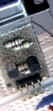
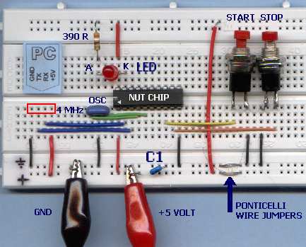
If you have already prepared the board for the experiment from part 1, it's only a matter of adding a copule of keys (ask your dealer for normally open buttons) to it. The kind shown in the photo required soldering some short wire to button pins, in order to fit breadboard pits. If you don't have a couple of buttons at hand, for testing purpose you can "simulate" them touching briefly the GND pis with wire tips. To START LED light, touch GND with the wire connected to Nutchip pin 8 (IN1); to STOP LED light, touch GND with the wire connected to pin 8 (IN2).
Parts listi
- DL1: LED diode
- R1: 390 ohm resistor, 1/4 W
- OSC1: 3-pin, 4 MHz ceramic resonator
- C1: 100 nF ceramic capacitor
- SW1, SW2: normally open key
- IC1: NUT01-AK (Nutchip)
You need also a 5 volt regulated power supply, a solderless breadboard, a programming interfaccia with cable, assorted color wire pieces, and a PC running Nutstation.
The START-STOP drive built on a breadboard
Please note the wire jumpers, needed by those breadboard because of separated left-right power rails. Check your breadboard against this interruption, or your prototype will refuse to react to button pressing!
At any time, a START-STOP ca be in one out of two states:
- drive is OFF, and could switch to ON should START button be pressed
- drive is ON, and could switch to OFF should STOP button be pressed
To write down with paper and pencil how it should work, we can state as follows:
STATE
OUTPUT
CONDITION
NEXT STATE
ST. 0
LED = OFF
(that is, OUT4 = 1)IF START IS PRESSED
(that is, IN1 = 0 )JUMP TO STATE ST. 1
ST. 1
LED = ON
(that is, OUT4 = 0)IF STOP IS PRESSED
(that is, IN2 = 0)JUMP TO STATE ST. 0
Speaking zero-one language - the only language a truth table speaks - we can say that as long as START is pressed, input IN1 is zero; and, in the same way, as long as STOP key is pressed, input IN2 is zero. As regards the LED, we have already seen how a LED connected to an output and the positive power supply is ON as long as the output is zero, and vice-versa.
Time to run Nutstation and to type the following truth table. Once finished, the table will look like this:
Type the comments in you native language: in english they sound as "LED is off, press START to switch it" and "LED is on, press STOP to switch it.". Comment are useful in order to understand better how a table works, especially if you need to modify many month after creating it, or if people other than the designer should need to modify or understand it.
When powered for first time, this table starts with the LED off. This is ruled by first table row, state zero, which is the RESET state.
Nota: the table file is "start_stop.nut". It is installed automatically by Nutstation, look in the folder "nutfiles". For more details about Nutstation click here.
Portatevi sulla pagina "Prog. chip" di Nutstation, e verificate nella finestra di "stato della programmazione" non vengano segnalati errori: se cos� non fosse, tornate sulla tavola della verit� e controllate di non avere commesso sviste, per esempio inserendo un numero di stato sbagliato.Collegate quindi l'interfaccia al PC con un cavo seriale.
Se non l'avete gi� fatto, inserite l'interfaccia sul circuito e accendete l'alimentazione a 5 volt (attenzione a non invertire la polarit�). Controllate che l'interfaccia sia regolarmente collegata al PC con un cavo seriale, infine fate click su "Programma Nutchip".
In pochi secondi la programmazione � completa e potete provare il vostro azionamento START-STOP.
A fun trait of Nutchips is they capability to modify the truth table in order to get thousand different behaviours with basically the same hardware. You can experiment new ways to program the circuit and invent new useful circuits.
On the previous article we have seen how to insert a timer into a truth table. Enter a "timed START STOP drive"! Here is how it works: pressing START, the LED turn on for 10 seconds - maximum. You can also switch it off before the time expires pressing STOP. The relevant file name is : start_10_stop.nut:
LED is off. Press START to switch it on. LED on. Press STOP to switch it off.
Alternately, wait 10 sec. and switch it off.
These were only appetizers. What about a mixed continuous/flashing drive? Pressing START, the LED turns on and stays still for 10 seconds. After that, it start flashing until STOP is pressed. If you are wondering what are the uses for such a logic, let us tell it is very appropriate to drive an heater. When first powered, the heater requires some time to assume its working temperature, therefore is kept ON without pauses. Once it reaches the working temperature, tough, it is pulsed in order not to overheat. Clever, isn't it?
Here is the related truth table, from the file start_flash_stop.nut.
LED off. Press START to switch it ON LED on. Press stop to switch it off.
Alternately, wait 10 seconds before switching to flash modeFlashing (OFF). Press stop to reset.
Alternately wait for next flashing phaseFlashing (ON). Press stop to reset.
Alternately wait for next flashing phase
A drawback of the previous table is the START button does not work when the LED is flashing. Can you tell why? Can you modify the table in order to make START working when the LEDis flashing?
One possible solution follows, it is from file start_flash_stop_2.nut:
LED off. Press START to switch it ON LED on. Press stop to switch it off.
Alternately, wait 10 seconds before switching to flash modeFlashing (OFF). Press stop to reset.
Press START to switch it steadily ON
Alternately wait for next flashing phaseFlashing (ON). Press stop to reset.
Alternately wait for next flashing phase
Congratulations, you have just completed lesson two of our three-step course. In the next step you will learn how to use an infrared remote control to control LED operation, building a remote-controlled LED.